Insulation framework and motor stator

A technology of insulating skeleton and motor stator, which is applied to the shape/style/structure of winding insulation, electrical components, electromechanical devices, etc., and can solve problems such as limited layout of crimping terminal slots, small adjustment space for parts, and weak structural strength. Achieve the effects of eliminating the space for embedded wires, improving the insulation withstand voltage level, and improving operational reliability

Active Publication Date: 2017-12-19
ZHUHAI GREE REFRIGERATION TECH CENT OF ENERGY SAVING & ENVIRONMENTAL PROTECTION
View PDF9 Cites 8 Cited by
  • Summary
  • Abstract
  • Description
  • Claims
  • Application Information

AI Technical Summary

Problems solved by technology

[0005] (1) The positions of the three terminal slots of the three-phase lead-out wire terminal slots of the above-mentioned existing insulating framework are in a "one"-shaped arrangement structure, which will result in the spatial distance between the crimping terminals in the three terminal slots and Creepage distances are short, resulting in insufficient insulation withstand voltage level of the motor
[0006] (2) The cross-section of the crimping terminal groove structure on the above-mentioned existing insulating frame is an "L"-shaped structure, and the structural strength of the "L"-shaped structure is relatively weak, and there are breakages during the assembly of the lead wire assembly and the transfer and transportation of the motor stator Hidden dangers
The two crimping terminal groove structures of the above-mentioned existing insulating frame are respectively located on the two opposite sides of the motor stator; while inside the compressor, the reserved space of the stator core in the direction of the four side lines is small, and the crimping terminal groove structure Installed at the edge position, there is a hidden danger of interference with other parts in the compressor. At the same time, this installation direction also restricts the layout of the crimping terminal slots, the utilization rate of the internal space of the compressor is low, and the parts adjacent to the insulating frame are adjusted. The space is small, which is not conducive to the miniaturization of the compressor

Method used


Image

  • Insulation framework and motor stator
  • Insulation framework and motor stator
  • Insulation framework and motor stator

Examples


Embodiment 1

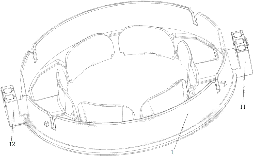
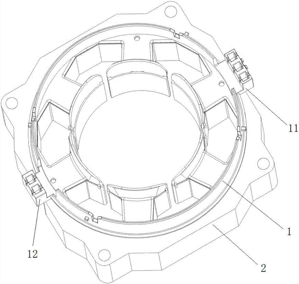
[0081] This embodiment provides an insulating frame used on a motor stator. Specifically, such as image 3 , Figure 6 , Figure 7 and Figure 10 As shown, the insulating frame in this embodiment includes an insulating frame body; wherein, the insulating frame body is provided with a three-phase lead wire terminal slot 34 for connecting the lead wire assembly. Wherein, three terminal slots 341 are provided on the three-phase lead wire terminal slot portion 34 , and each terminal slot 341 is used for installing crimping terminals. Wherein, the centers of the three terminal grooves 341 on the three-phase lead wire terminal groove portion are not on a straight line (that is, the centers of the three terminal grooves are respectively three vertices of a triangle. The " Center" is defined as follows: first, when the three terminal slots 341 are regular slots, the "center" of each terminal slot 341 is the centroid of the terminal slot, and at this time, the centroid of each term...

Embodiment 2

[0086] Preferably, this embodiment provides an insulating frame. Compared with the previous embodiment, this embodiment designs the insulating frame body as follows:

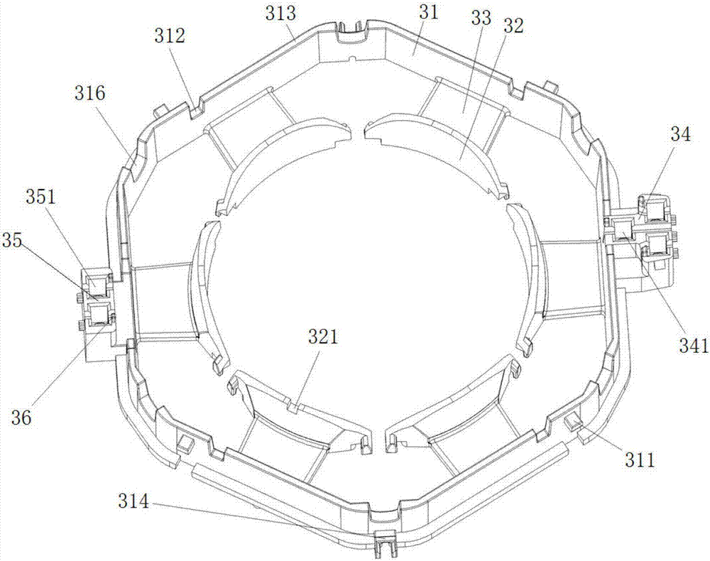
[0087] Such as Figure 3 to Figure 5 As shown, the insulating frame body in this embodiment includes a first annular wall 31 , a second annular wall 32 and a plurality of connecting pieces 33 for connecting the first annular wall 31 and the second annular wall 32 . Wherein, the second annular wall 32 is located inside the first annular wall 31 . One end of the connecting piece 33 is connected to the first annular wall 31 , and the other end is connected to the second annular wall 32 . Moreover, the connecting piece 33 is used as a winding portion of the insulating frame for winding the stator winding.

[0088] Preferably, the connecting piece 33 serves as the bottom plate of the insulating frame. The second annular wall 32 includes a plurality of second walls arranged at intervals; wherein, the number of the ...

Embodiment 3

[0091] Preferably, this embodiment provides an insulating skeleton, compared with the previous embodiment, such as image 3 , Figure 6 , Figure 7 to Figure 8 As shown, the present embodiment further designs the three-phase lead wire terminal slot 34 as follows:

[0092]As described in Embodiment 1, the three terminal slots 341 on the three-phase lead wire terminal slot portion 34 in this embodiment are respectively the first terminal slot, the second terminal slot and the third terminal slot. Wherein, the groove wall of the first terminal groove is connected with the first annular wall 31 . There is a gap between the second terminal slot, the third terminal slot and the first annular wall 31 , and the gap is used for passing wires so as to insert the winding wires into the second terminal slot and the third terminal slot. Wherein, the center of the first terminal groove is equivalent to the vertex of a triangle formed by connecting the centers of the three terminal groove...


PUM


Abstract

The invention relates to an insulation framework and a motor stator, and relates to the technical field of a motor. The insulation framework comprises an insulation framework main body, wherein a three-phase leading-out line terminal slot part is arranged on the insulation framework main body, three terminal slots are formed in the three-phase leading-out line terminal slot part, a line pressing terminal is arranged in each terminal slot, and the centers of the three terminal slots in the three-phase leading-out line terminal slot part are not in a straight line. The motor stator comprises the insulation framework. By the insulation framework, the creepage distance among the line pressing terminals in the three terminal slots in the three-phase leading-out line terminal slot part of the insulation framework can be effectively extended, so that the insulation pressure-resistant grades among three-phase winding enameled wires and among the line pressing terminals are improved, and finally, the running reliability of the motor is improved.

Description

technical field [0001] The invention relates to the technical field of motors, in particular to an insulating frame and a motor stator. Background technique [0002] An electric motor is a rotating electrical machine that converts electrical energy into mechanical energy. The motor is generally composed of two parts: the motor stator and the rotor; among them, the motor stator mainly includes the stator core, windings and insulating frame; and the insulating frame is an injection molded part placed at both ends of the stator core and has a wire-passing design. [0003] figure 1 It is an insulating skeleton commonly used on motor stators in the prior art. Such as figure 1 As shown, the existing insulating frame 1 is provided with two integrated crimping terminal slot structures. One of the crimping terminal slots with two slots is a neutral terminal slot 12 for fixing the neutral short-circuit end of the stator winding. Another three-slot crimping terminal groove structu...

Claims


Application Information

Patent Timeline
Patent Type & Authority Applications(China)
IPC IPC(8): H02K3/52H02K3/34
CPCH02K3/345H02K3/522
Inventor 张凯高明世陈华杰
Owner ZHUHAI GREE REFRIGERATION TECH CENT OF ENERGY SAVING & ENVIRONMENTAL PROTECTION
Why Eureka
Try Eureka