LED vehicle lamp module heat dissipation control method and device

A technology of LED car lights and control methods, which is applied in the direction of lighting devices, fixed lighting devices, cooling/heating devices of lighting devices, etc., and can solve the problems of high set power and rotating speed of cooling fans, energy waste, and reduced fan life. To achieve the effect of increasing LED luminous flux output, ensuring driving safety and reducing requirements

Inactive Publication Date: 2017-12-22
SAIC MOTOR
View PDF11 Cites 3 Cited by
  • Summary
  • Abstract
  • Description
  • Claims
  • Application Information

AI Technical Summary

Problems solved by technology

[0003] 1. Active cooling is mainly based on the cooling fan. This type of cooling fan will work at full power as long as the headlights are turned on. No matter what the external environment is, it will easily cause energy waste and reduce the life of the fan.
[0004] 2. Passive heat dissipation is mainly based on metal heat sinks with high thermal conductivity. In order to meet the conditions of the limit state of the car, the heat sink block has a large volume and weight. Severe attenuation or LED damage
[0005] 3. The current limiting heat dissipation of the circuit mainly uses the thermistor as a sensor to control the LED current by detecting the temperature. Although the LED is protected from heat damage, it will cause a sharp drop in luminous flux, affecting normal lighting requirements, and posing a safety hazard
Most of the existing radiators are controlled only by simply correlating the temperature with the radiator speed, without actually considering the fan performance, temperature sensor position and the influence of the power of the LED itself. The set power and speed of the cooling fan are often high. Unable to meet the requirements of lightweight and energy saving and environmental protection

Method used


Image

  • LED vehicle lamp module heat dissipation control method and device
  • LED vehicle lamp module heat dissipation control method and device
  • LED vehicle lamp module heat dissipation control method and device

Examples


Embodiment 1

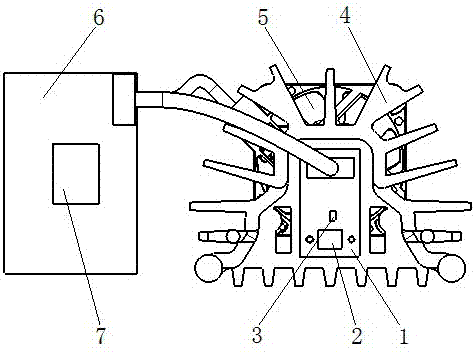
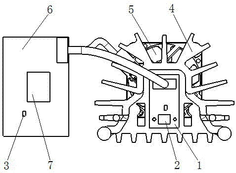
[0031] Such as figure 1 , the conventional LED car light module includes a PCB board 1 carrying a light source, the PCB board 1 is an aluminum substrate, a copper substrate, a steel substrate or a multi-layer FR4, and the PCB board 1 is equipped with a light source LED chip 2 and a temperature sensor 3 , the PCB board 1 is surrounded by a cooling fin group 4, and the back of the PCB board 1 is equipped with a cooling fan 5; the driving module 6 and the controller 7 are electrically connected to the light source LED chip 2, the temperature sensor 3 and the cooling fan 5;

[0032] Such as figure 2 As shown, when the heat dissipation fan 5 is not working, the temperature sensor 3 directly installed on the PCB board 1 can accurately measure the temperature of the light source area in the LED lamp module, but once the heat dissipation fan 5 is turned on, the heat dissipation area of ​​the fan will Directly corresponding to the temperature sensor 3 will cause the temperature senso...


PUM


Abstract

The invention relates to the field of vehicle illuminating lamp heat dissipation, in particular to an LED vehicle lamp module heat dissipation control method and device. According to the LED vehicle lamp module heat dissipation control method, the standard work temperature TL, the standard work current IL and the limit working temperature Tmax of an LED vehicle lamp module, and the limit rotation speed rmax of a heat dissipation fan are set, and the heat dissipation fan is controlled according to the temperature Tj in the LED vehicle lamp module; when Tj is smaller than or equal to TL, the heat dissipation fan does not work; when Tj is larger than TL and r is smaller than rmax, a controller controls the heat dissipation fan to be started, r is equal to f(Tj), and Ij is equal to IL; when Tj is larger than TL and r is equal to rmax, the controller controls the current Ij of the LED vehicle lamp module to be lowered gradually till r is smaller than rmax; and when Tj is equal to Tmax, Ij is lowered to 0. According to the LED vehicle lamp module heat dissipation control method and device, the temperature is controlled to below the limit temperature through the controllable heat dissipation fan, the requirement for a heat dissipation assembly is lowered, the size can be reduced, and the lightweight need is also met. Meanwhile, on the premise that the heat dissipation ability can be met, LED luminous flux output is further increased, illuminance is improved, and driving safety is ensured.

Description

technical field [0001] The invention relates to the field of heat dissipation of vehicle lighting lamps, in particular to a heat dissipation control method and device for an LED vehicle light module. Background technique [0002] Due to regulations and lighting requirements on the luminous flux output of LED headlights, only high-power LEDs can meet the demand, but if high-power LEDs are not cooled in time, the output of LED luminous flux will be affected, and extreme conditions may cause LED damage. At present, there are three types of cooling systems for LED headlights on the market: active cooling, passive cooling, and circuit current limiting: [0003] 1. Active cooling is mainly based on the cooling fan. This type of cooling fan will work at full power as long as the headlights are turned on. No matter what the external environment is, it will easily cause energy waste and reduce the life of the fan. [0004] 2. Passive heat dissipation is mainly based on metal heat si...

Claims


Application Information

Patent Timeline
Patent Type & Authority Applications(China)
IPC IPC(8): F21S8/10F21V29/61F21V29/74F21W101/02F21W101/10F21Y115/10
CPCF21V29/61F21V29/74F21Y2115/10
Inventor 张胜伟王猛李雷刘俊华朱诚诚
Owner SAIC MOTOR
Why Eureka
Try Eureka