Real-time in situ picosecond laser pulse auto-correlation meter

A picosecond laser and autocorrelator technology, applied in instruments and other directions, can solve the problems of high cost, cumbersome operation, complex system, etc., and achieve the effects of easy construction, high measurement accuracy, high sensitivity and resolution

Inactive Publication Date: 2017-12-22
INST OF CHEM CHINESE ACAD OF SCI
View PDF7 Cites 5 Cited by
  • Summary
  • Abstract
  • Description
  • Claims
  • Application Information

AI Technical Summary

Problems solved by technology

[0005] In view of the above analysis, the present invention aims to provide a real-time in-situ picosecond laser pulse autocorrelator to solve the problems of high cost, complex system and cumbersome operation of existing equipment

Method used


Image

  • Real-time in situ picosecond laser pulse auto-correlation meter
  • Real-time in situ picosecond laser pulse auto-correlation meter

Examples


Embodiment Construction

[0034] Preferred embodiments of the present invention will be specifically described below in conjunction with the accompanying drawings, wherein the accompanying drawings constitute a part of the application and are used together with the embodiments of the present invention to explain the principles of the present invention.

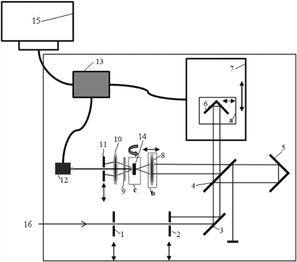
[0035] In this embodiment, the real-time in-situ picosecond laser pulse autocorrelator, such as figure 1 As shown, it mainly includes a first incident light stop 1, a second incident light stop 2, a reflector 3, a beam splitter 4, a rectangular prism 5, a retroreflector 6, a precision displacement platform 7, a first lens 8, Optical filter 9, second lens 10, diaphragm 11, photodiode detector 12, data acquisition and control system 13, frequency doubling crystal 14 and computer 15, wherein, the first incident light diaphragm 1, the second incident light light Diaphragm 2, mirror 3, beam splitter 4, rectangular prism 5, retroreflector 6, precision displa...


PUM


Abstract

The invention relates to a real-time in situ picosecond laser pulse auto-correlation meter. An incident light diaphragm component, a reflection mirror and a beam splitter are sequentially fixed along the advancing direction of incident pulse laser. The incident pulse laser is split into a first beam of light and a second beam of light through the beam splitter. The first beam of light is reflected to a right angle prism through the beam splitter, is reflected to the beam splitter through the right angle prism, and finally is transmitted to a first lens through the beam splitter. The second beam of light is transmitted to a retroreflector through the beam splitter, is reflected to the beam splitter through the retroreflector, and finally is reflected to the first lens through the beam splitter. The first beam of light and the second beam of light converge at a frequency doubling crystal through the first lens to produce a second harmonic signal. The second harmonic signal sequentially passes through a filter, a second lens, a diaphragm and a photodiode detector to generate an electrical signal, and the electrical signal is collected by a master control system. The real-time in situ picosecond laser pulse auto-correlation meter provided by the invention has the advantages of simple structure, low cost, easy operation, easy setting up, easy debugging, wide application range, and can continuously change the time range of the measured laser pulse.

Description

technical field [0001] The invention relates to the technical field of measuring picosecond laser pulse width, in particular to a real-time in-situ picosecond laser pulse autocorrelator. Background technique [0002] The time width of picosecond laser pulse is an important basic index to measure laser pulse. Due to its extremely narrow pulse width, which is only tens or more than a hundred picoseconds, picosecond pulse laser has high peak power and high spectral resolution, and has great potential in the study of ultrafast chemical reaction kinetics and high-resolution medical coherent imaging. its unique advantages. The stability of the picosecond laser pulse width is an important indicator of the mode-locking stability of the picosecond laser, and the corresponding pulse width detection and monitoring are the prerequisites for using the picosecond laser. Existing photodetectors and broadband oscilloscopes cannot meet such measurement requirements due to their complicated...

Claims


Application Information

Patent Timeline
Patent Type & Authority Applications(China)
IPC IPC(8): G01J11/00
CPCG01J11/00
Inventor 李亦易张贞王鹏郭源刘鸣华
Owner INST OF CHEM CHINESE ACAD OF SCI
Why Eureka
Try Eureka