
Nano cutting depth high-speed single-point scratch test device and test method thereof

A test device and nanotechnology, applied in the direction of measuring device, test material hardness, instrument, etc., can solve the problem of controlling the length of the scratch, the limited feeding speed of the scratching tool in the ball-on-disc scratching method, and the single pendulum scratching method Limiting the sampling frequency of the radius of rotation of the scratching tool, etc., to achieve the effect of controllable scratching length, reduced action time, and clear corresponding relationship

Active Publication Date: 2017-12-22
DALIAN UNIV OF TECH
View PDF10 Cites 12 Cited by
  • Summary
  • Abstract
  • Description
  • Claims
  • Application Information

AI Technical Summary

Problems solved by technology

[0008] 1) The single-point scratching test based on AFM or nano-indenter and other precision instruments is limited by the principle of linear scratching motion, and it is impossible to achieve the scratching speed of abrasive particles in the order of m / s in the actual grinding process
[0009] 2) The single pendulum scratching method is limited by the radius of gyration of the scratching tool and the sampling frequency of the dynamometer, and cannot accurately collect scratching force signals under different nanometer depths of cut under high-speed scratching conditions
[0010] 3) The ball-on-disc scratching method is limited by the feed speed of the scratching tool, and cannot effectively control the scratch length under high-speed scratching conditions, making it very difficult to find the feature points of the scratched residual contour under the microscope

Method used


Image

  • Nano cutting depth high-speed single-point scratch test device and test method thereof
  • Nano cutting depth high-speed single-point scratch test device and test method thereof
  • Nano cutting depth high-speed single-point scratch test device and test method thereof

Examples


Embodiment Construction

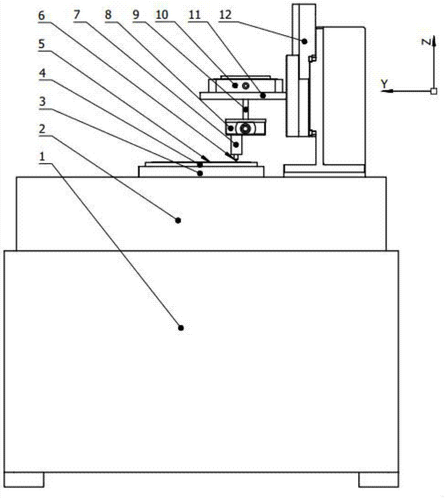
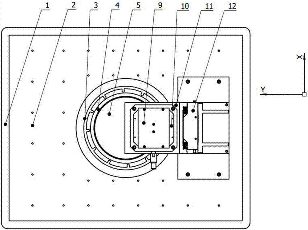
[0081] The present invention will be further described below in conjunction with the accompanying drawings. Such as Figure 1-4 As shown, a nanometer depth of cut high-speed single-point scratch test device, including:

[0082] base 1;

[0083] The horizontally placed workbench 2 is fixedly installed on the top surface of the base 1;

[0084] The vertically placed air-floating turntable 3 is fixedly installed on the workbench 2;

[0085] The test piece fixture 4 is installed on the top end surface of the air-floating turntable 3, and is coaxial with the air-floating turntable 3, and the test piece fixture 4 is driven to rotate by the air-floating turntable 3; the test piece fixture 4 is a vacuum chuck, a magnetic chuck or a mechanical structural fixtures;

[0086] The test piece 5 is mounted on the test piece fixture 4;

[0087] The Z-direction feeding device 12 is installed on the top surface of the workbench 2, and feeds along the direction of the rotation axis of the a...


PUM

PropertyMeasurementUnit
lengthaaaaaaaaaa
heightaaaaaaaaaa
widthaaaaaaaaaa

Abstract

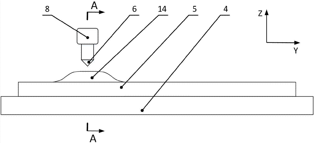
The invention discloses a nano cutting depth high-speed single-point scratch test device and a test method thereof. The device comprises a workbench, an air flotation rotary table, a test piece fixture, a test piece, a Z-direction feeding device, a nano motion platform, a force sensor and a scratch tool, wherein a micro convex structure with controllable length and height is machined in the to-be-scratched position of the test piece. The scratch speed is increased from mu m / s to m / s, and the machining speed of abrasive particles in the ultra-precise grinding process is restored really. Scratch force signals under different nano cutting depth conditions are accurately collected under the high-speed scratch condition, and the scratch force-scratch depth correspondence is explicit. The micro convex structure is constructed on the surface of the test piece, the condition that very long scratches are left on the surface of the whole wafer by a diamond needle point is avoided, abundant test data are provided in shorter scratches, the content of effective information in the unit scratch length is greatly increased, following scratch analysis and feature identification of remaining scratches are facilitated, and the integrity of the scratch tool is guaranteed.

Description

technical field [0001] The invention belongs to the field of material testing and ultra-precision machining in mechanical processing, and in particular relates to a nanometer depth-of-cut high-speed single-point scratch test device and a test method thereof. Background technique [0002] Ultra-precision grinding can efficiently remove material with nanoscale depth of cut, so as to obtain high shape accuracy and surface quality, and is one of the important processes for precision parts processing. The essence of its processing mechanism is that a large number of abrasive particles of different shapes on the surface of the abrasive tool participate in the cutting process at a cutting depth of nanometer level. Therefore, in the research of ultra-precision grinding mechanism, people often design nano-depth single-point scratch test as an important means to understand the ultra-precision grinding process. Throughout the literature at home and abroad, the single-point scratch tes...

Claims


Application Information

Patent Timeline
Patent Type & Authority Applications(China)
IPC IPC(8): G01N15/10
CPCG01N15/10G01N3/46G01N2203/0286G01N15/1023
Inventor 周平黄宁康仁科郭东明闫英
Owner DALIAN UNIV OF TECH
Learn More