
Automatically-controlled high-stability pressure-maintaining core-removing device

A coring device and high-stability technology, which is applied in the direction of undisturbed core extraction, earthwork drilling and mining, etc., can solve problems such as damage to the pressure-holding mechanism, insufficient compacting force, and impact of flip cover, achieving good sealing and convenient operation and use , good sealing effect

Pending Publication Date: 2017-12-26
SICHUAN UNIV
View PDF0 Cites 9 Cited by
  • Summary
  • Abstract
  • Description
  • Claims
  • Application Information

AI Technical Summary

Problems solved by technology

After the cover of the pressure-holding cylinder is closed, a closed pressure-holding environment is formed. It is necessary to make the cover have a certain pre-tightening pressure to prevent the pressure-holding failure caused by the gap around the cover when the pressure difference between the inside and outside of the pressure-holding cylinder is small.
Most of the traditional clamshells rely on their own gravity or torsion spring to press, often the pressing force is not enough, and there is no external auxiliary pressing device
A small number of pressure-holding cylinder devices rely on the gravity of the rock sample to freely fall to compress the cover. During the pressing process, it is easy to have a large impact on the cover, resulting in damage to the pressure-holding mechanism.

Method used


Image

  • Automatically-controlled high-stability pressure-maintaining core-removing device
  • Automatically-controlled high-stability pressure-maintaining core-removing device
  • Automatically-controlled high-stability pressure-maintaining core-removing device

Examples


Embodiment Construction

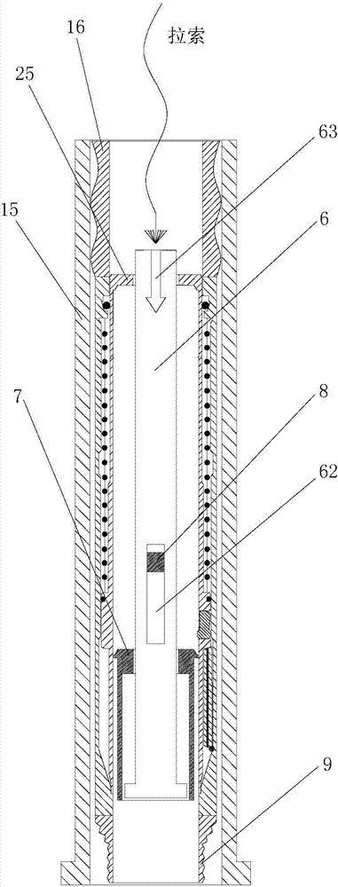
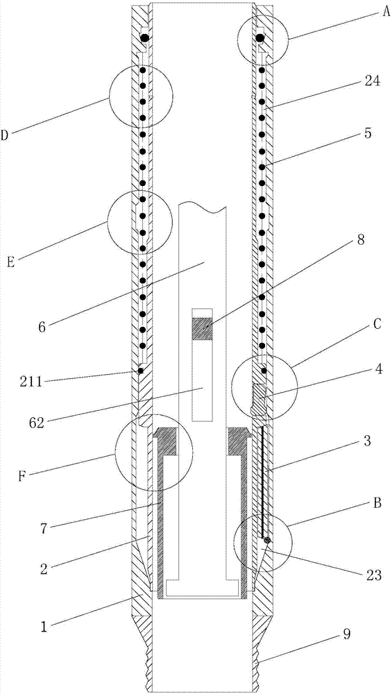
[0025] Such as Figures 1 to 8 As shown, the automatically controlled high-stability pressure-holding coring device of the present invention includes a pressure-holding outer cylinder 1, a pressure-holding inner cylinder 2, a flip cover 3, a slider 4, a spring 5, a central rod 6, a PVC pipe 7, an energy storage device 8 and PDC bit 9.

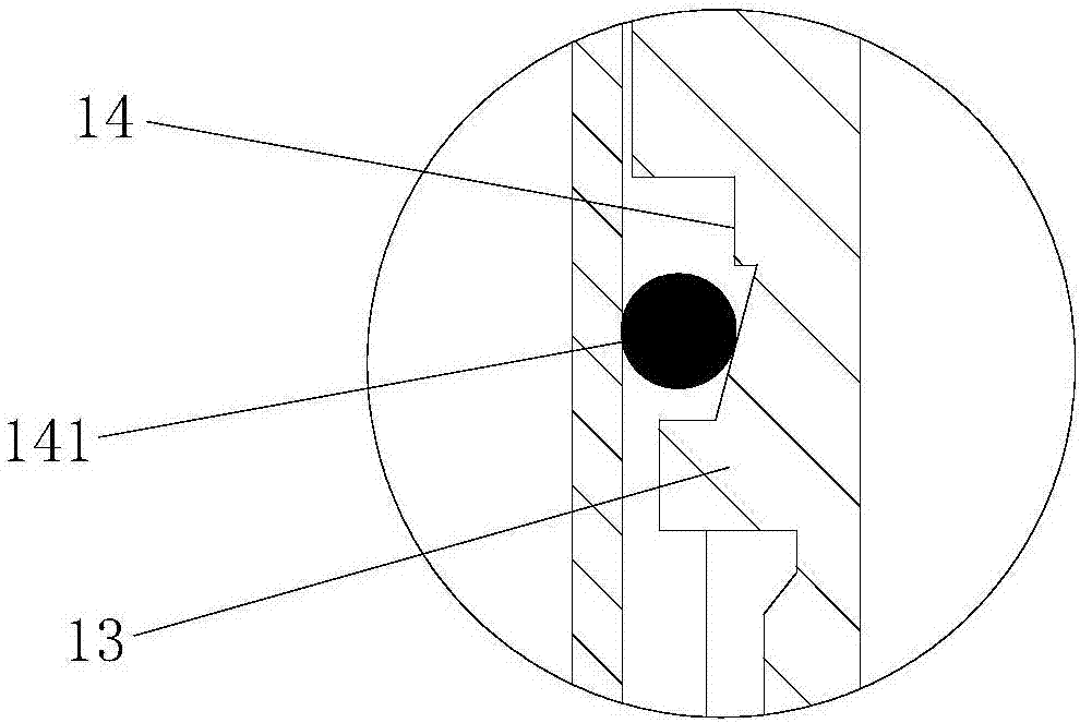
[0026] The pressure-holding outer cylinder 1 has an integral structure, wherein the inner wall of the lower section is provided with a mounting groove 11 along the circumferential direction, the inner wall of the middle and upper section is provided with a groove 12 along the circumferential direction, and the inner wall of the top end protrudes outward to form a raised portion 13 of the outer cylinder. A trapezoidal valve port 14 is opened in the middle and lower section of 13 along the circumference; a sealing ring 141 is embedded inside the trapezoidal valve port 14, and the upper end inner wall of the pressure maintaining outer cylinder 1 i...


PUM


Abstract

The invention relates to an automatically-controlled high-stability pressure-maintaining core-removing device. The device comprises an outer pressure-maintaining cylinder, an inner pressure-maintaining cylinder, an overturn cover, sliding blocks and springs; a mounting groove is formed in the inner wall of the lower middle section of the outer pressure-maintaining cylinder in the circumferential direction, the inner wall of the top end of the outer pressure-maintaining cylinder protrudes outwards to form an outer cylinder protruding part, and trapezoidal valve ports are formed in the lower middle section of the outer cylinder protruding part in the circumferential direction; sealing rings are embedded in the trapezoidal valve ports; the outer wall of the lower middle section of the inner pressure-maintaining cylinder protrudes outwards in the circumferential direction to form an inner cylinder protruding part; an overturn cover containing cavity is formed between the mounting groove and the outer wall, located at the lower side of the inner cylinder protruding part, of the inner pressure-maintaining cylinder; spring containing cavities are formed between the outer walls of the middle and upper sections of the inner pressure-maintaining cylinder and the inner walls of the middle and upper sections of the outer pressure-maintaining cylinder; key grooves are formed in the circumference of the inner cylinder protruding part at equal distances; the overturn cover is contained in the overturn cover containing cavity in a matched mode; the sliding blocks are assembled in the key grooves; the springs are contained in the spring containing cavities in a matched mode. The automatically-controlled high-stability pressure-maintaining core-removing device is simple and reasonable in structural design, good in sealing performance and convenient and reliable to operate and use.

Description

technical field [0001] The invention belongs to the field of pressure-holding equipment, and in particular relates to an automatically controlled high-stability pressure-holding coring device. Background technique [0002] The formation pressure in deep and deep sea areas is high. When sampling the rock formations in this area, in order to ensure that the collected rock samples are still in a high-pressure environment after reaching the ground, it is necessary to use the pressure-holding core barrel to store and transport the samples. The pressure-holding coring cylinder is hoisted vertically into the deep coring area. When the rock sample is pulled into the pressure-holding cylinder, the pressure-holding cylinder is flipped and closed to form a high-pressure environment inside the cylinder. There is usually a large amount of fluid in the deep abyssal area, so the maintained pressure often exists in the form of water pressure. Since the sampling area is located in a deep ar...

Claims


Application Information

Patent Timeline
IPC IPC(8): E21B25/00E21B25/18
CPCE21B25/00E21B25/18
Inventor 谢和平陈领高明忠华夏明传舰李聪何志强鲁义强
Owner SICHUAN UNIV
Features
  • Generate Ideas
  • Intellectual Property
  • Life Sciences
  • Materials
  • Tech Scout
  • Unparalleled Data Quality
  • Higher Quality Content
  • 60% Fewer Hallucinations
Learn More