Ultrasonic transmitting circuit for medical ultrasonic diagnosis

A technology of transmitting circuit and ultrasonic diagnosis, applied in the directions of acoustic wave diagnosis, infrasound wave diagnosis, diagnosis, etc., can solve the problems of poor echo performance and low acoustic wave energy, and achieve the effect of good echo quality, uniform acoustic wave and good echo performance.

Inactive Publication Date: 2017-12-29
易之医疗科技无锡有限公司
View PDF5 Cites 1 Cited by
  • Summary
  • Abstract
  • Description
  • Claims
  • Application Information

AI Technical Summary

Problems solved by technology

[0005] However, the existing ultrasonic transmitting circuit for medical ultrasonic diagnosis uses the positive piezoelectric effect of piezoelectric ceramics to convert the reflected sound wave into an electrical signal, the transmitted sound wave energy is small, and the echo performance is poor

Method used


Image

  • Ultrasonic transmitting circuit for medical ultrasonic diagnosis
  • Ultrasonic transmitting circuit for medical ultrasonic diagnosis
  • Ultrasonic transmitting circuit for medical ultrasonic diagnosis

Examples


Embodiment 1

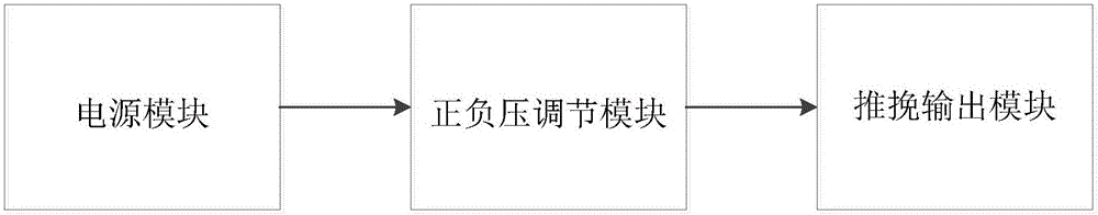
[0048] The positive and negative voltage adjustment module adjusts the output voltages of the first power supply unit VCC and the second power supply unit VEE at the power supply end according to the amplitude difference of the measured positive and negative voltages of the transmitted waveform, so that the positive and negative voltages generated by the push-pull output module The excitation pulse of high voltage is symmetrical.

Embodiment 2

[0050] The problem of inconsistent positive and negative voltages is solved by connecting resistors in series with the positive and negative high voltage power supplies of each channel. By adjusting the resistance connected in series to the high-voltage power supply, the positive and negative high voltages of the final excitation pulse of each channel are symmetrical and consistent.

[0051] Specifically, as attached Figure 6 As shown, the positive and negative pressure adjustment module includes a first adjustment unit and a second adjustment unit, and the first adjustment unit corresponds to the attached Figure 6 middle resistor R3, the second adjustment unit corresponds to the attached Figure 6 Middle resistor R4. The first adjustment unit R3 is arranged between the first power supply unit and the NMOS transistor Q1, the first power supply unit VCC, the first adjustment unit R3 and the NMOS transistor Q1 form a first path, and the one adjustment unit R3 is used for Ad...

Embodiment 3

[0055] The shorter the excitation pulse, the higher the longitudinal resolution of the ultrasonic image, but the NMOS transistor Q1 and PMOS transistor Q2 are packaged in the IC and cannot be modified, and the MOSFET device itself is between the gate and the source, the gate and the drain There are parasitic capacitances between the poles, which are the gate capacitance (Ciss and the drain capacitance Crss, respectively, as shown in the attached Figure 7 As shown, if the MOSFET is turned on, the gate capacitance Crss needs to be charged first. If a resistor is added between the drain and the gate, when the current of the control signal flows into the gate, due to the resistance between the drain and the gate The charging current will be increased, and the conduction time of the MOSFET can be shortened, thereby shortening the excitation pulse.

[0056] Based on the above analysis, this embodiment further sets a third adjustment unit and a fourth adjustment unit in the transmit...


PUM


Abstract

The invention relates to an ultrasonic transmitting circuit for medical ultrasonic diagnosis. The transmitting circuit comprises a push-pull output module, a positive-negative-pressure regulating module and a power module, wherein the push-pull output module is used for producing exciting pulses of positive and negative pressures, and the positive-negative-pressure regulating module is used for regulating the positive and negative pressures of the push-pull output module, so that the exciting pulses of the positive and negative pressures produced by the push-pull output module are symmetrical. The power module is used for providing voltage for the transmitting circuit. The sound wave energy outwards propagated by the transmitting circuit is increased, so that sound waves are uniform, and echo quality is improved. In addition, the connecting time of NMOS and PMOS transistors is shortened and the exciting pulses are shortened by increasing connecting-charging currents of the NMOS and PMOS transistors of the push-pull output module, and accordingly the longitudinal resolution of ultrasonic images is improved.

Description

technical field [0001] The invention relates to the technical field of medical ultrasonic diagnosis, in particular to an ultrasonic transmitting circuit for medical ultrasonic diagnosis. Background technique [0002] The frequency range of sound waves that the human ear can perceive is 20-20000Hz. Below 20Hz is called infrasound, above 20000Hz is called ultrasonic. Ultrasound is a kind of mechanical wave. The principle of medical ultrasonic diagnosis is to use the inverse piezoelectric effect of piezoelectric ceramics inside the probe to excite high-frequency electrical pulses in the form of sound waves. The sound wave propagates in the organ tissue, and at the same time its intensity is modulated by the acoustic impedance characteristics of the tissue and reflected back. Using the positive piezoelectric effect of piezoelectric ceramics, the reflected sound wave is converted into an electrical signal, and the received echo is converted into an electrical signal. Wave signa...

Claims


Application Information

Patent Timeline
Patent Type & Authority Applications(China)
IPC IPC(8): A61B8/00
CPCA61B8/4444
Inventor 毛建智赵兵
Owner 易之医疗科技无锡有限公司
Why Eureka
Try Eureka