
Emulsifying device

An emulsification device and the technology of the first fluid, applied in the directions of transportation and packaging, chemical instruments and methods, chemical/physical processes, etc., can solve the problems of unsatisfactory emulsification effect, achieve the effect of reducing pressure drop and improving emulsification effect

Inactive Publication Date: 2017-12-29
NORTH CHINA ELECTRIC POWER UNIV (BAODING)
View PDF0 Cites 0 Cited by
  • Summary
  • Abstract
  • Description
  • Claims
  • Application Information

AI Technical Summary

Problems solved by technology

Therefore, the emulsification effect is not ideal

Method used


Image

  • Emulsifying device
  • Emulsifying device

Examples


Embodiment Construction

[0014] Embodiments of the present invention are described below with reference to the drawings, in which like parts are denoted by like reference numerals. In the case of no conflict, the following embodiments and the technical features in the embodiments can be combined with each other.

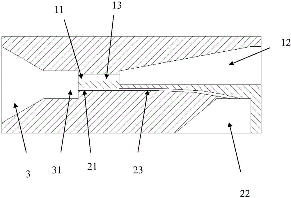
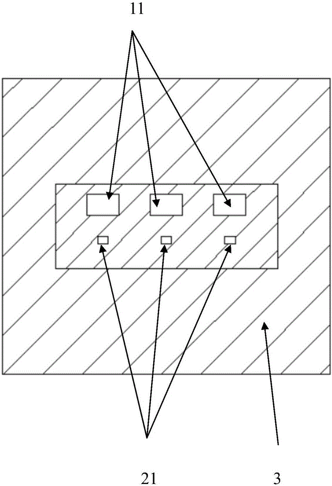
[0015] figure 1 shows the structural diagram of the emulsification device of the present invention, to be precise, figure 1 is a side sectional view. The emulsifying device of the present invention comprises: a first fluid channel 13 for high-viscosity fluid, a second fluid channel 23 for low-viscosity fluid, the fluid inlet end of the first fluid channel 13 is connected to the first fluid guide 12, The fluid inlet end of the second fluid channel 23 is connected to the second fluid guide 22 . The first fluid outlet 11 of the first fluid channel 13 and the second fluid outlet 21 of the second fluid channel 23 are commonly connected to the diversion header 3 . The diversion header 3 is loc...


PUM

PropertyMeasurementUnit
diameteraaaaaaaaaa

Abstract

The invention relates to micromixer techniques and provides an emulsifying device. The emulsifying device comprises a first fluid passage (13) for high-viscosity fluids, a second fluid passage (23) for low-viscosity fluids, a first fluid director (12), a second fluid director (22) and a flow guide chamber (3). A fluid inlet end of the first fluid passage (13) is connected to the first fluid director (12), a fluid inlet end of the second fluid passage (23) is connected to the second fluid director (22), and first fluid outlets (11) of the first fluid passage (13) and second fluid outlets (21) of the second fluid passage (23) are jointly connected to the flow guide chamber (3). The emulsifying device has advantages that oil phase pressure drop is reduced, and mixing effects are improved.

Description

technical field [0001] The invention relates to the microstructure emulsification technology in the field of chemical industry, and more specifically relates to an emulsification device suitable for high-viscosity oil phase fluid. Background technique [0002] The microstructure reactor has good heat and mass transfer characteristics due to its large specific surface area, and generally has a microstructure with an equivalent diameter of less than 500 μm. According to the function, it can be mainly divided into micro reactor, micro heat exchanger, micro mixer and so on. Emulsification can be achieved with a micro mixer. The oil-water two-phase is emulsified by a micro mixer. Most of the existing micro-mixers are designed based on the fact that the viscosity coefficients of the two fluids are not much different. When emulsifying with a micro mixer, if the viscosity of the oil phase is high, most of the energy is consumed in the channel instead of dissipated in the mixing c...

Claims


Application Information

Patent Timeline
Patent Type & Authority Applications(China)
IPC IPC(8): B01F3/08B01F13/00
CPCB01F23/4145B01F23/4105B01F23/41B01F33/3017B01F33/30B01F2101/48
Inventor 栗永利杨春笋张辉张振明张锴杜小泽杨勇平
Owner NORTH CHINA ELECTRIC POWER UNIV (BAODING)
Learn More