
Efficient large selective laser melting forming device

A laser melting and selective technology, applied in the direction of manufacturing auxiliary devices, improving energy efficiency, improving process efficiency, etc., can solve problems such as damage, complex structure, interruption of processing process, etc., to save the use of inert gas and improve the compactness of structure 、To overcome the effect of small forming size

Active Publication Date: 2017-12-29
CHONGQING UNIV
View PDF8 Cites 11 Cited by
  • Summary
  • Abstract
  • Description
  • Claims
  • Application Information

AI Technical Summary

Problems solved by technology

[0003] Due to the limitations of the scanning range of the optical galvanometer scanning system and the effective blowing and smoking range, the forming size of selective laser melting equipment in the world is limited to a small size range. For example, the maximum forming size of the EOS selective laser melting equipment M400 of the German 3D printing company Size 400mm×400mm, SLM solutions company SLM500 maximum forming size 500mm×280mm, Concept Laser company X LINE 2000R maximum forming size 800mm×400mm, large selective laser melting equipment is yet to be developed
[0004] In order to develop large-scale selective laser melting equipment, there is a multi-galvanometer structure in the prior art. Although this can be adapted to the forming of large-sized workpieces, due to the increase in the size range, there is too much smoke in the forming chamber, and the The laser system is extremely sensitive to dust, and excessive dust can easily cause greater damage. This requires timely and effective cleaning of a large amount of smoke generated during laser processing, otherwise it will seriously affect the quality of formed parts , It will even cause the interruption of the processing process, and the selective laser melting process is carried out in an inert gas atmosphere, so the selective laser melting equipment needs a high-efficiency laser smoke filtration system to achieve both filtering smoke and inert gas recycling
[0005] Although in the prior art, there is also a laser melting device that can remove the smoke and dust in the forming chamber, but its structure is complicated, and because it is also installed in the forming chamber, and in order to better ensure the dust collection effect, it is necessary to install the dust collection device Set it as close to the table of the forming table as possible, so that it is easy to hinder the reciprocating movement of the scraper during the powder spreading process during use; moreover, the laser melting equipment in the prior art that can eliminate the smoke and dust in the forming chamber is also not suitable for large-scale Formed parts, cannot form a good fit with the existing multi-galvanometer structure

Method used


Image

  • Efficient large selective laser melting forming device
  • Efficient large selective laser melting forming device
  • Efficient large selective laser melting forming device

Examples


Embodiment Construction

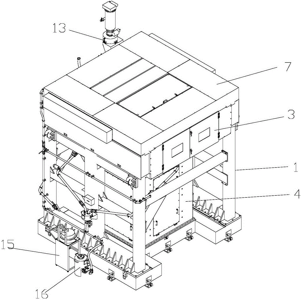
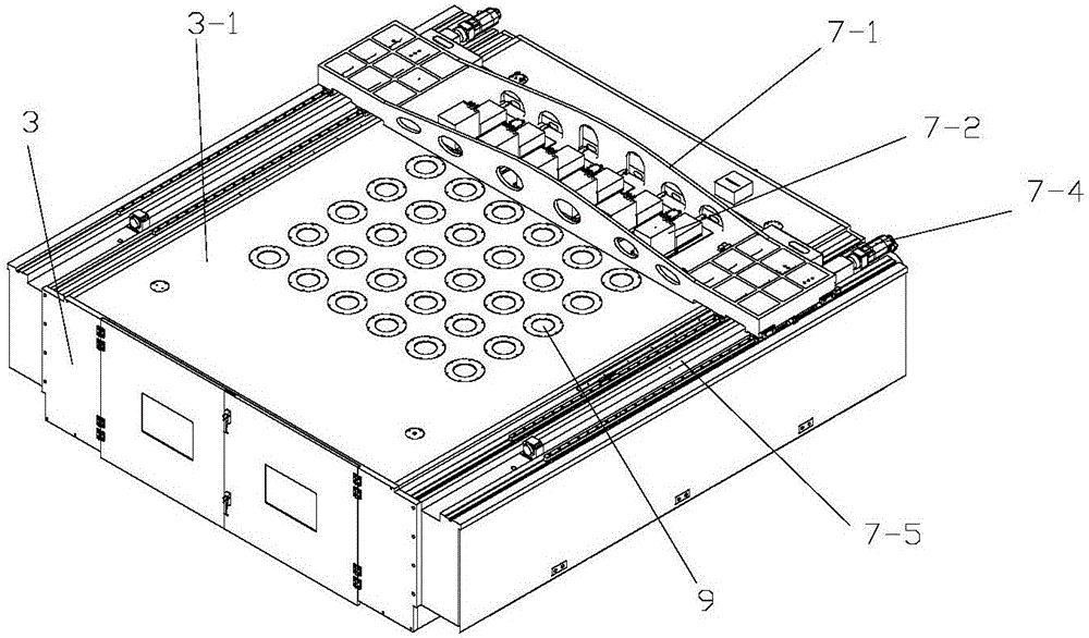
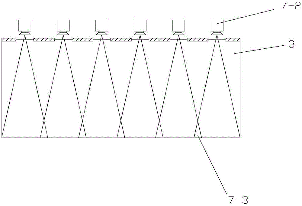
[0036] figure 1 It is a schematic diagram of the overall structure of the present invention, figure 2 It is a schematic diagram of the overall structure of the vibrating mirror scanning device in the present invention, image 3 It is a schematic diagram of the working state of the vibrating mirror scanning device in the present invention, Figure 4 It is a schematic diagram of scanning the overlapping area of ​​the galvanometer scanning device in the present invention, Figure 5 It is a structural schematic diagram of the blowing and smoking mechanism in the present invention, Figure 6 It is a structural schematic diagram of the filtering device in the present invention, Figure 7 It is a working schematic diagram of the powder circulation system in the present invention, Figure 8 It is a schematic diagram of the installation structure of the powder circulation system in the present invention, Figure 9 It is a schematic diagram of the forming workbench movement in the...


PUM


Abstract

The invention discloses an efficient large selective laser melting forming device. A galvanometer scanning device can move in a reciprocating mode in the powder laying direction to achieve the multi-station working state, thus large part forming can be achieved, and the problem of the small forming size of a single galvanometer system is solved; the galvanometer scanning device is overall arranged outside a forming bin, thus the inert gas protection space can be reduced, inert gas is saved, and the forming bin is compact in structure; meanwhile, a smoke blowing and sucking mechanism arranged in the forming bin can synchronously move with the galvanometer scanning device to the same station, and when laser sintering is conducted at the different stations, smoke dust discharging can be smoothly achieved; and a smoke blowing and sucking rack of the smoke blowing and sucking mechanism can move up and down relative to a supporting plate, when a scraper works, the scraper can be avoided, work of the smoke blowing and sucking rack is not interfered mutually with work of the scraper, and the overall structure compactness of the forming bin is greatly improved.

Description

technical field [0001] The invention relates to the field of selective laser melting, in particular to a high-efficiency large-scale selective laser melting forming device. Background technique [0002] Selective laser melting, also known as SLM, is a technology that uses metal powder to be completely melted under the heat of a laser beam, then cooled and solidified to form a shape. Under the action of high laser energy density, the metal powder is completely melted, and after heat dissipation and cooling, it is metallurgically welded with solid metal. It is through this process that selective laser melting forms a three-dimensional entity layer by layer. According to the layered slicing information of the 3D CAD model of the molded part, the scanning system controls the laser beam to act on the powder in the area to be formed. After one layer of scanning is completed, the working platform will drop a distance after one layer and then the powder feeding system will deliver a...

Claims


Application Information

Patent Timeline
IPC IPC(8): B22F3/105B33Y30/00B33Y50/02
CPCB33Y30/00B33Y50/02B22F10/00B22F12/49B22F10/30B22F12/50B22F12/44B22F10/73B22F12/90B22F12/67B22F12/70B22F10/28B22F2999/00B22F10/77B22F2203/03Y02P10/25B29C64/153B29C64/357B29C64/364B33Y40/00B22F12/222B22F12/224
Inventor 张正文张鹏刘飞戴京伟马治博李忠华魏东华张涛任治好
Owner CHONGQING UNIV
Learn More