Foot-stand mechanism of unmanned aerial vehicle

A technology of unmanned aerial vehicle and tripod, applied in the field of unmanned aerial vehicle, can solve the problems of large space occupied by the tripod, damage of the unmanned aerial vehicle, inconvenient storage, etc., and achieve the effect of being easy to store, not easily damaged, and preventing transmission problems.

Active Publication Date: 2017-12-29
POWERVISION ROBOT INC
View PDF10 Cites 0 Cited by
  • Summary
  • Abstract
  • Description
  • Claims
  • Application Information

AI Technical Summary

Problems solved by technology

[0003] The lower end of the existing aircraft is equipped with a tripod to facilitate the landing of the aircraft. However, in the existing aircraft, the extended tripod is fixedly connected to the fuselage. After use, it is necessary to store the UAV. , because the tripod takes up a lot of space, it is inconvenient to store, and it is easy to cause damage to the drone

Method used


Image

  • Foot-stand mechanism of unmanned aerial vehicle
  • Foot-stand mechanism of unmanned aerial vehicle

Examples


Embodiment 1

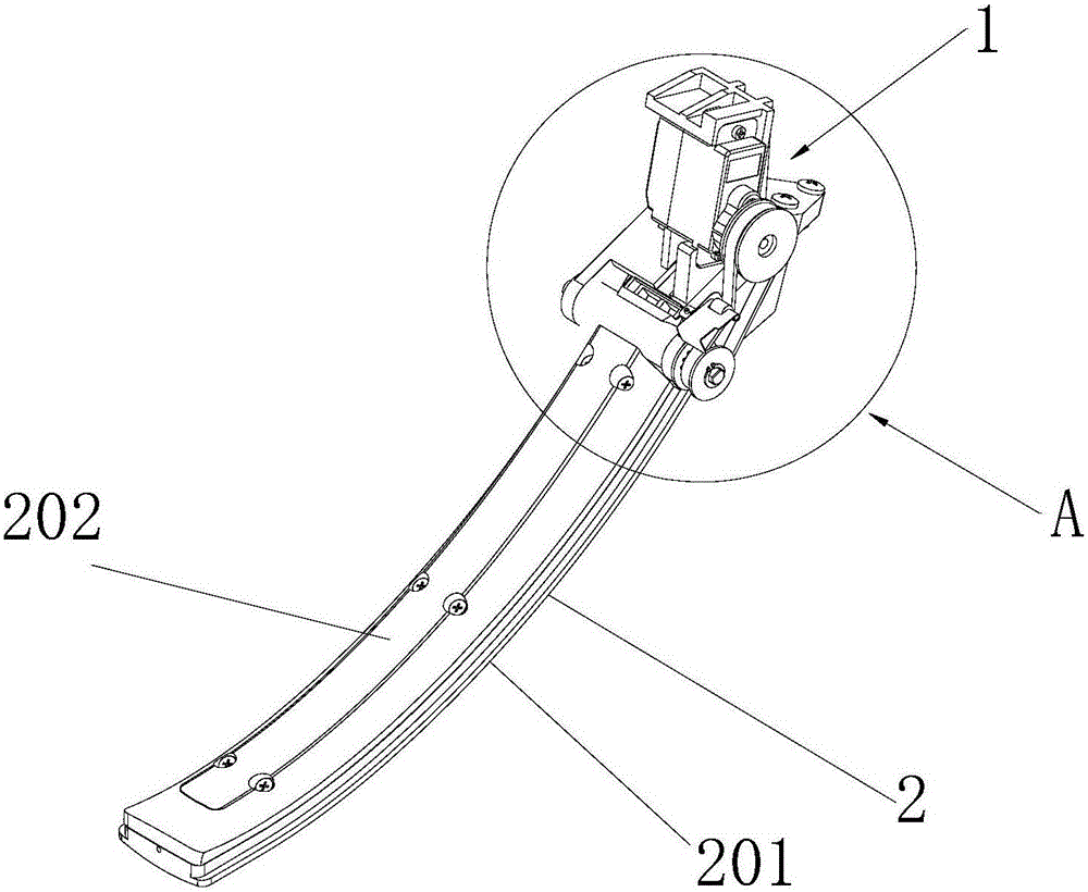
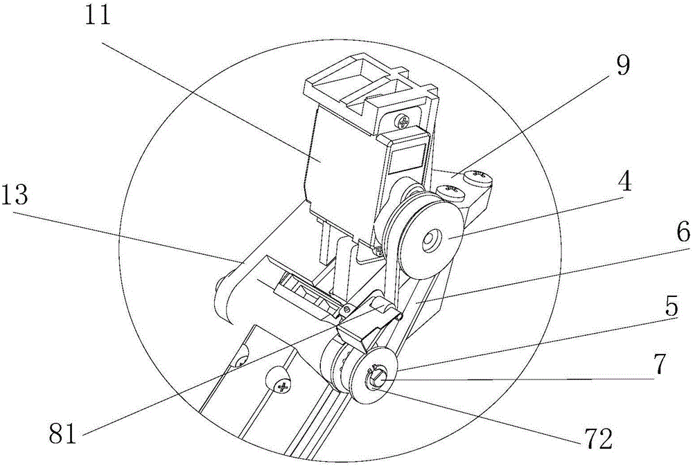
[0032] Such as figure 1 with figure 2 As shown in the schematic diagram of the tripod mechanism, the tripod mechanism of the unmanned aerial vehicle of the present invention includes a stand 1 fixed on the main body of the drone and a stand 2 hinged to the stand 1 and a stand 2 arranged on the stand 1 and The transmission mechanism between the tripods 2 includes: a motor 11 fixed on the support 1, a driving wheel 4 fixedly connected to the motor shaft, and a driven wheel 5 arranged coaxially with the footrest shaft 7. The driving Power is transmitted between the wheel 4 and the driven wheel 5 through a bendable power transmission mechanism to control the extension and recovery of the tripod 2. Preferably, the transmission mechanism is a timing belt transmission mechanism, the bendable power transmission mechanism is a belt 6 provided with cogging, and the driving wheel 4 and the driven wheel 5 are provided with cogging meshing with the belt 6 The driving wheel 4 rotates throu...

Embodiment 2

[0035] Such as figure 1 with figure 2 As shown in the schematic diagram of the tripod mechanism, the connecting arm 13 is provided with a shaft hole, and the tripod 2 is rotatably fixed on the connecting arm 13 through a tripod shaft 7 arranged in the shaft hole. At least one end of the tripod shaft 7 Extending from the outer side of the connecting arm 13. The driven wheel 5 is fixed on the part of the stand shaft 7 located outside the connecting arm 13, and the driving wheel 4 and the driven wheel 5 are located in the same plane. A limit surface is provided on the part of the tripod shaft 7 located outside of the connecting arm 13, and the axis of the driven wheel 5 can be attached to the limit surface and pass through the limit surface to limit it and the tripod shaft 7 During the relative rotation between the two, the tripod shaft 7 and the tripod 2 rotate integrally, and the extension and retraction of the tripod 2 are controlled by this. The tripod shaft 7 is also provi...


PUM


Abstract

The invention discloses a foot-stand mechanism of an unmanned aerial vehicle. The foot-stand mechanism comprises a support, a foot stand and a transmission mechanism, wherein the support is fixed to a main body of the unmanned aerial vehicle, the foot stand is rotatably connected with the support, and the transmission mechanism is arranged between the support and the foot stand. The transmission mechanism comprises a motor fixed to the support, a driving wheel fixedly connected with a motor shaft and a driven wheel, wherein the driven wheel and a rotary shaft of the foot stand are coaxially arranged, and the driving wheel and the driven wheel are connected through a bendable power transmission mechanism arranged between the driving wheel and the driven wheel in a sleeving mode. According to the foot-stand mechanism of the unmanned aerial vehicle, the function that the foot stand of the unmanned aerial vehicle can be folded is achieved, the foot stand of the unmanned aerial vehicle can be folded when not being used, the occupied space of the unmanned aerial vehicle is reduced, and storing is convenient and the foot stand is not liable to be damaged.

Description

Technical field [0001] The invention relates to the field of unmanned aerial vehicles, in particular to a tripod mechanism of an unmanned aerial vehicle. Background technique [0002] At present, aircraft or unmanned aerial vehicles have been more and more widely used in social life, for close observation of places that are difficult for people to reach, or high-altitude aerial photography, thereby providing convenience for observation and shooting. [0003] The lower end of the existing aircraft is equipped with a tripod to facilitate the landing of the aircraft. However, in the existing aircraft, the extended tripod is fixedly connected to the fuselage. After use, the drone needs to be stored. , Because the tripod occupies a large space, it is inconvenient to store and easily cause damage to the drone. Therefore, designing an unmanned aerial vehicle that is easy to store and carry safely when not in use has become an important research direction, and designing an extendable and ...

Claims


Application Information

Patent Timeline
Patent Type & Authority Applications(China)
IPC IPC(8): B64C25/10B64C25/24
CPCB64C25/10B64C25/24
Inventor 郑卫锋其他发明人请求不公开姓名
Owner POWERVISION ROBOT INC
Why Eureka
Try Eureka