
Converter gas recovery control method

A converter gas and control method technology, applied in the manufacture of converters, etc., can solve the problems of small fan motor work, high flue gas temperature, and fan air volume limitations, so as to reduce CO pollutant emissions, improve economic and technical indicators, and improve gas consumption. The effect of recovery volume

Inactive Publication Date: 2017-12-29
HBIS COMPANY LIMITED HANDAN BRANCH COMPANY
View PDF6 Cites 5 Cited by
  • Summary
  • Abstract
  • Description
  • Claims
  • Application Information

AI Technical Summary

Problems solved by technology

In the prior art, the fan has been running at high speed during the converter steelmaking process, while the converter is in the smelting period, the flue gas temperature is high, the gas density is low, and there is a pressure of about 3KPa inside the gas cabinet during the gas recovery, and the fan motor works during the gas recovery Small, low fan current
However, when the converter is inverting, measuring temperature, and sampling, the flue gas temperature is relatively low, and the gas density is relatively high. In addition, when it is vented directly to the air, the work of the fan motor is relatively large, and the current of the fan is relatively high.
When the flue gas is diffused, the current of the fan motor has reached the rated value, while the current of the fan motor is 6-8 amps lower than the rated value during gas recovery. The power of the fan cannot be fully utilized during gas recovery, and the air volume of the fan is limited, which affects Converter gas recovery

Method used


Image

  • Converter gas recovery control method

Examples


Embodiment Construction

[0014] The present invention will be described in further detail below in combination with specific embodiments.

[0015] The control method of the converter gas recovery adopts the following process: (1) The chain control is no longer based on a single gas concentration but combined with the chain control of steelmaking recovery time and gas recovery: when the converter smelting time is less than or equal to 60 seconds, the gas is released; When the converter smelting time is 60-240 seconds, the gas is recovered when the CO concentration rises to >6%, and the gas is released when the CO concentration drops to 9 When the CO concentration is reduced to 12%, the gas is recovered, and the CO concentration is reduced to <10%, and the gas is released; when the converter is smelting When performing gas recovery, if the converter stops smelting, if other gas recovery conditions permit, continue to recover gas for 50 seconds, and release the gas after 50 seconds.

[0016] Take the co...


PUM


Abstract

The invention discloses a converter gas recovery control method. The converter gas recovery control method comprises the following steps: a converter gas recovery system controls gas recovery and diffusion through a control system; when the converter smelting time is less than or equal to 60 seconds, gas is diffused; when the converter smelting time is 60-240 seconds, gas is recovered when the CO concentration rises to be more than 6%, and gas is diffused when the CO concentration is reduced to be less than 4%; when the converter smelting time is 240-550 seconds, gas is recovered when the CO concentration rises to be more than 9%, and gas is diffused when the CO concentration is reduced to be less than 7%; and when the converter smelting time is more than or equal to 550 seconds, gas is recovered when the CO concentration rises to be more than 12%, and gas is diffused when the CO concentration is reduced to be less than 10%. According to the converter gas recovery control method, the relationship between the CO concentration and the recovery time is established, a recovery program no longer performs linkage according to only the gas concentration but performs linkage control according to both the steel-making time and gas recovery, and the gas recovery quantity can be increased to the maximum extent, so that gas can be recovered as much as possible on the basis of ensuring safe gas, the gas recovery quantity is increased, and energy saving and consumption reduction are realized.

Description

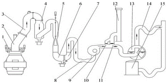
technical field [0001] The invention relates to a waste gas recovery method, in particular to a control method for converter gas recovery. Background technique [0002] The converter gas recovery process is mainly to collect the flue gas generated at the furnace mouth of the converter. After cooling and dust removal through the vaporization flue and vaporization dust removal system, the qualified converter gas is transported to the gas cabinet of the energy center through the fan. After the converter gas is pressurized by the gas cabinet pressurizer, it is sent to the gas users such as the heating furnace of the steel rolling mill, the hot blast stove of the blast furnace, and the CCPP power plant. figure 1 As shown, the converter gas recovery process generally adopts the following process: the flue gas generated during the converter smelting process is collected through the movable hood 1, and enters the first-stage venturi tube and gravity dehydrator 4 through the furnace ...

Claims


Application Information

Patent Timeline
Patent Type & Authority Applications(China)
IPC IPC(8): C21C5/38
CPCC21C5/38
Inventor 朱坦华周素强易勇孙兴旺杨卫华王存明李威远刘璋锁刘志峰
Owner HBIS COMPANY LIMITED HANDAN BRANCH COMPANY
Learn More