Acceleration measurement method and device based on atomic interference in optical waveguide

A technology of acceleration measurement and optical waveguide, which is applied in the direction of acceleration measurement using inertial force, which can solve the problems of complex structure, large well depth, and large accumulated error for a long time, so as to improve the measurement sensitivity, the system structure is simple, and the measurement reduction is achieved. effect of error

Inactive Publication Date: 2017-12-29
NAT UNIV OF DEFENSE TECH
View PDF4 Cites 11 Cited by
  • Summary
  • Abstract
  • Description
  • Claims
  • Application Information

AI Technical Summary

Problems solved by technology

This kind of accelerometer relies on the gyro torque to balance the inertia moment. It can maintain high measurement accuracy in a large range, but the structure is complex, the volume is large, and the price is relatively expensive.
At the same time, these accelerometers also have common shortcomings: 1. The long-term cumulative error is large; 2. The measurement sensitivity is far from the upper limit of quantum sensors.
The measurement accuracy of this type of scheme is mainly limited by the following two aspects: firstly, the potential well roughness of the magnetic field waveguide will cause decoherence and splitting of atomic groups in the condensed state; secondly, due to the large well depth of this type of magnetic trap, will cause a phase shift in atomic interactions
Adding current modulation in the kHz range to the trapped magnetic field current source can make the potential well smooth, but at the same time, it will introduce unnecessary heating effect to the atomic group, which will have a large negative impact, reduce the signal-to-noise ratio of interferometry, and thus affect the measurement sensitivity.

Method used


Image

  • Acceleration measurement method and device based on atomic interference in optical waveguide
  • Acceleration measurement method and device based on atomic interference in optical waveguide
  • Acceleration measurement method and device based on atomic interference in optical waveguide

Examples


preparation example Construction

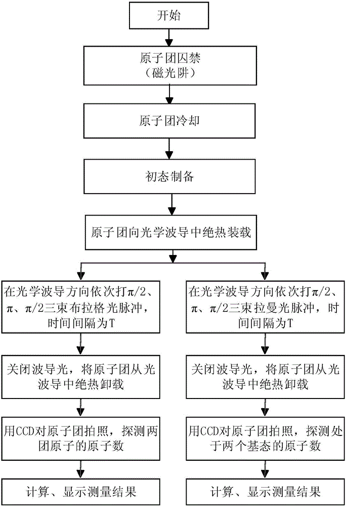
[0035] S1. Preparation of cold atomic groups.

[0036] Firstly, it is necessary to carry out pre-cooling (to obtain cold atomic groups with a temperature of about 20μk) through classical magneto-optic traps (MOT for short) and Polarization Gradient Cooling (PGC for short), and then the The temperature of the atomic group is further reduced (50nK-10μk) by means of evaporative cooling, optical lattice cooling or sideband cooling.

[0037] S2. Preparation of the initial state and loading of the optical waveguide.

[0038] Prepare the atomic group in a magnetically insensitive state|F=1,m F =0>, then open the optical waveguide, and pack the atomic groups into the optical waveguide. Wherein, preferably, the direction of the optical waveguide is horizontal, forming an included angle of 90 degrees with the direction of gravity.

[0039] S3, atomic interference.

[0040] Two beams of Raman light or Bragg light respectively apply three beams of light pulses of π / 2, π and π / 2 to the...

Embodiment 1

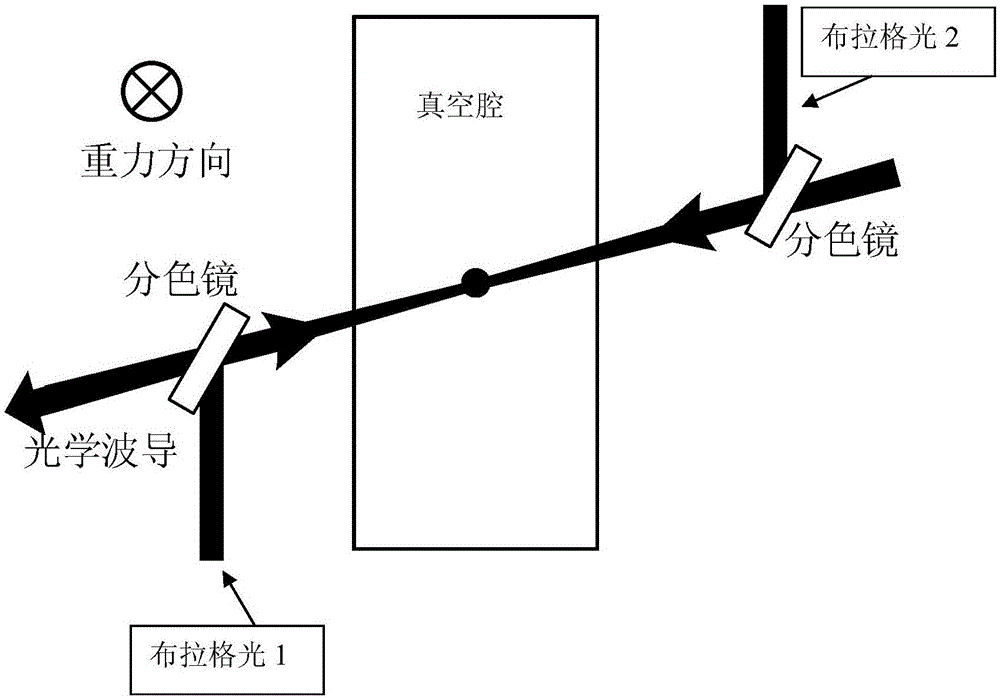
[0045] Embodiment 1: as figure 2 As shown, the acceleration measurement device based on atomic interference in the optical waveguide of the present invention includes:

[0046] Vacuum cavities for lasers that create optical waveguides;

[0047] Two phase-locked Bragg lights, the frequency difference of the two Bragg lights is several KHz;

[0048] Optical waveguide, the direction of the optical waveguide is any horizontal direction, and the optical waveguide is equipped with atomic groups; the atomic group is a group of cooled atomic groups (temperature is 50nK ~ 10μk), which is in a magnetically insensitive state after state preparation|F=1, m F =0>.

[0049] Preferably, in a preferred embodiment, the potential well depth of the optical waveguide should be greater than the temperature of the atomic groups, so that the atomic groups can exist in the optical waveguide for a longer time without escaping from the waveguide.

[0050] In a specific application example, three o...

Embodiment 2

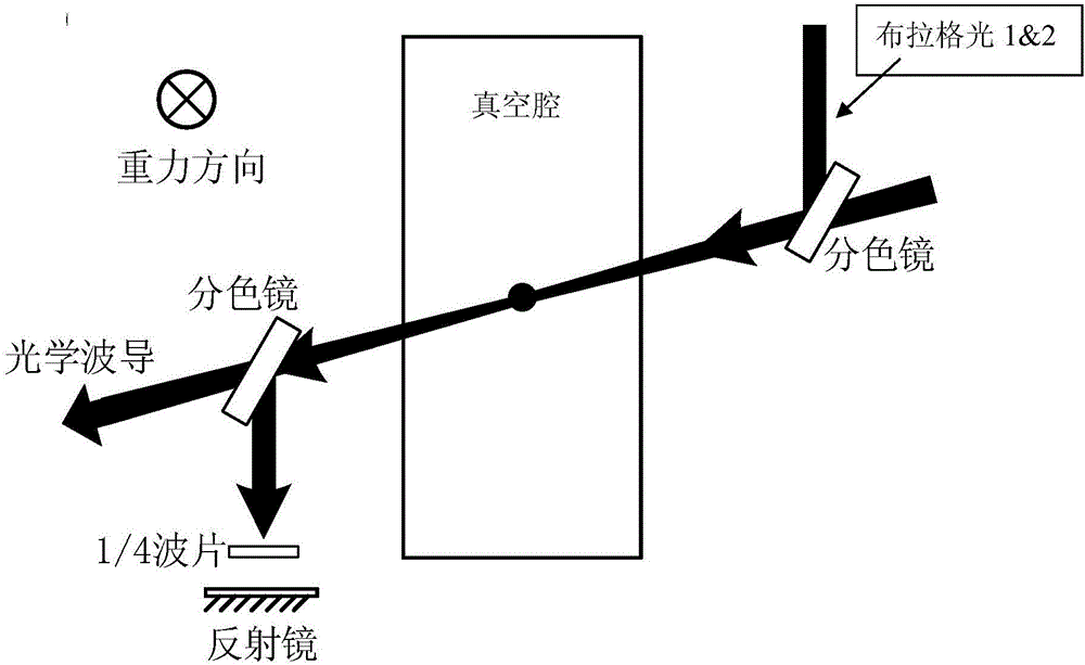
[0051] Embodiment 2: as image 3 As shown, the acceleration measurement device based on atomic interference in the optical waveguide of the present invention includes:

[0052] Vacuum cavities for lasers that create optical waveguides;

[0053] Two phase-locked Bragg lights, the frequency difference of the two Bragg lights is several KHz.

[0054] Optical waveguide, the direction of the optical waveguide is any horizontal direction, and the optical waveguide is equipped with atomic groups; the atomic group is a group of cooled atomic groups (temperature 50nK ~ 10μk), which is in a magnetically insensitive state after state preparation|F=1,m F =0>.

[0055] Preferably, in a preferred embodiment, the potential well depth of the optical waveguide should be greater than the temperature of the atomic groups, so that the atomic groups can exist in the optical waveguide for a longer time without escaping from the waveguide.

[0056] In a specific application example, three optical...


PUM


Abstract

The invention discloses an acceleration measurement method based on atomic interference in an optical waveguide, which includes the following steps: S1, preparing a cold atomic group; S2, loading an optical waveguide: keeping the atomic group in a magnetic insensitive state, opening the optical waveguide, and putting the atomic group in the optical waveguide; S3, atomic interference: applying PI/2, PI and PI/2 light pulses to the atomic group through two beams of Raman light or Prague light to realize beam splitting and combining of the atomic group, and constructing an atom interferometer; and S4, imaging detection: after interference, letting the atomic group freely fall for a period of time, carrying out detection through CCD or PD, and calculating the axial acceleration of the optical waveguide according to the detection result. The method and the device have the advantages of simple principle, simple operation, high accuracy, and the like.

Description

technical field [0001] The invention mainly relates to the field of acceleration measurement equipment, in particular to an acceleration measurement method and device based on atomic interference in an optical waveguide. Background technique [0002] At present, most of the accelerometers on the market adopt traditional technology, and their main working principles include (1) vibrating wire type: a linear accelerometer supported by two identical string wires. String tension is greatly affected by material properties and temperature, so a precise temperature control device and string tension adjustment mechanism are required. (2) Pendulum integrating gyroscope: an instrument that uses a two-degree-of-freedom gyroscope with a certain pendulum on the rotation axis to measure acceleration. This kind of accelerometer relies on the gyro torque to balance the inertia moment. It can maintain high measurement accuracy in a large range, but the structure is complex, the volume is la...

Claims


Application Information

Patent Timeline
Patent Type & Authority Applications(China)
IPC IPC(8): G01P15/03
CPCG01P15/03
Inventor 颜树华魏春华贾爱爱罗玉昆胡青青朱凌晓王恩龙李期学杨俊
Owner NAT UNIV OF DEFENSE TECH
Why Eureka
Try Eureka