Wall-mounted wireless router for enhancing antenna signal intensity

A wireless router and signal strength technology, applied in radio relay systems, supporting machines, passive power relay systems, etc., can solve the problems of occupying space, inconvenient for cleaning, unstable antenna transmission network signals, etc., to save The effect of footprint and signal strength enhancement

Inactive Publication Date: 2017-12-29
SHENZHEN SHENGLU IOT COMM TECH CO LTD
View PDF7 Cites 15 Cited by
  • Summary
  • Abstract
  • Description
  • Claims
  • Application Information

AI Technical Summary

Problems solved by technology

However, such a placement method not only occupies the space on the ground or the desktop, but also is not convenient for cleaning. When cleaning, it is easy to touch the router and make the antenna transmit network signals unstable.
In addition, the height of the desktop and the ground is relatively lo

Method used


Image

  • Wall-mounted wireless router for enhancing antenna signal intensity
  • Wall-mounted wireless router for enhancing antenna signal intensity
  • Wall-mounted wireless router for enhancing antenna signal intensity

Examples


Embodiment 1

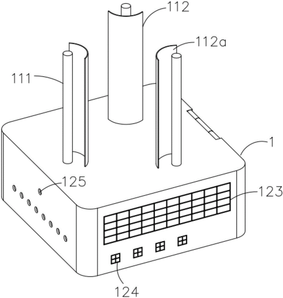
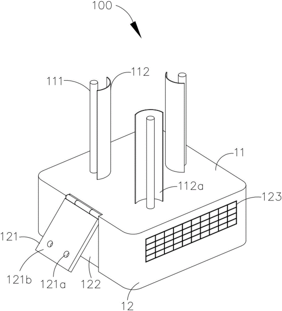
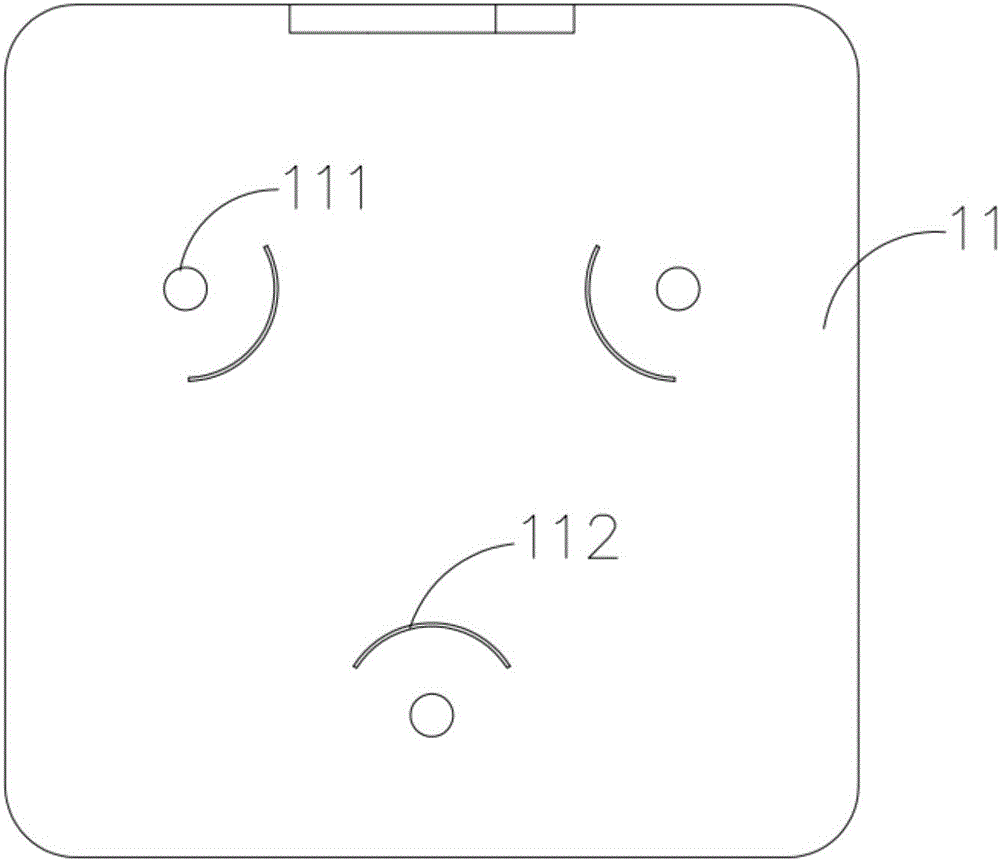
[0041] Please also refer to Figure 1 to Figure 3, is a schematic structural diagram of a wall-mounted wireless router 100 that enhances antenna signal strength provided in Embodiment 1 of the present invention. The wall-mounted wireless router 100 that enhances antenna signal strength includes a housing 1, a connecting board 121, and a plurality of antennas 111 And several reflecting plates 112. The connecting plate 121 is connected with the housing 1 , and the connecting plate 121 is provided with at least one hanging member 121 a for hanging the housing 1 on the wall. Each antenna 111 is arranged on the casing 1, and several antennas 111 are arranged in a ring shape along the center of the casing 1 and enclose to form a first area, and each reflector 112 is arranged on the casing 1 and is located in the first area , and each radiation plate is set corresponding to each antenna 111 , and each reflection plate 112 is used to shield the corresponding antenna 111 , so that eac...

Embodiment 2

[0070] see figure 2 , Figure 4 as well as Figure 5 Embodiment 2 of the present invention provides a wall-mounted wireless router 200 with enhanced antenna signal strength. The wall-mounted wireless router 200 with strong antenna signal strength in Embodiment 2 of the present invention and the wall-mounted wireless router 200 with strong antenna signal The Wall Wireless Router 100 differs in that:

[0071] Each reflector 212 is set corresponding to each antenna 111 respectively, and each reflector 212 is located between two adjacent antennas 111, so as to block the adjacent two antennas 111, and each reflector 212 extends in its height direction The height above is greater than the height of the antenna 111 corresponding to it, so as to completely cover the antenna 111 corresponding to it, and each reflector 212 includes at least one metal reflective surface 212a, and each metal reflective surface 212a faces the antenna 111 corresponding to it. set up.

[0072] Preferabl...


PUM


Abstract

The invention discloses a wall-mounted wireless router for enhancing antenna signal intensity. The wireless router comprises a shell, a connecting plate, a plurality of antennas and a plurality of reflecting plates. The connecting plate is connected with the shell, and the connecting plate is provided with at least one hanging element used for hanging the shell on the wall. Each antenna is arranged on the shell, the centers of several antennas are annularly arranged along the center of the shell and are enclosed to form a first area, the reflecting plates are arranged on the shell and are located in the first area, the reflecting plates are arranged to correspond to the antennas, and the reflecting plates are used for shielding the corresponding antennas, so that the antennas are separated by the reflecting plates. The heights of the reflecting plates on the height extension direction are greater than those of the correspondingly arranged antennas, and the reflecting plates comprise metal reflecting surfaces, and the metal reflecting surfaces are arranged to face to the correspondingly arranged antennas. The wireless router provided by the embodiment of the invention can be suspended on the wall, thereby saving space and enhancing the antenna signal intensity.

Description

technical field [0001] The invention relates to the technical field of network equipment, in particular to a wall-mounted wireless router for enhancing antenna signal strength. Background technique [0002] A wireless router is a router that has a wireless network coverage function and can transmit broadband network signals to wireless network devices (such as tablets, laptops, smart phones, etc.) within a certain area through an antenna. [0003] Since the current wireless routers on the market do not have supporting or suspendable components, the wireless routers are usually placed on the ground or on the table indoors. However, such a placement method not only occupies the space on the ground or the desktop, but also is not convenient for cleaning. When cleaning, it is easy to touch the router and make the antenna transmit network signals unstable. In addition, the height of the desktop and the ground is relatively low compared to the height of the entire indoor space. I...

Claims


Application Information

Patent Timeline
IPC IPC(8): H04L12/771F16M13/02H04B7/145H04L45/60
CPCH04B7/145H04L45/60F16M13/02
Inventor 杜光东
Owner SHENZHEN SHENGLU IOT COMM TECH CO LTD
Why Eureka
Try Eureka