Eureka AIR delivers breakthrough ideas for toughest innovation challenges, trusted by R&D personnel around the world.

Efficient treatment discharging device for petrochemical wastewater

A petrochemical and discharge device technology, which is applied in water/sewage treatment, water/sludge/sewage treatment, natural water treatment, etc., can solve the problems of low sewage discharge efficiency, manpower and material resources consumption, environmental hazards, etc., and achieve reduction The number of dismantling inspections, the improvement of emission efficiency, and the effect of high-efficiency emission

Inactive Publication Date: 2018-01-05
新乡市巨能合成材料有限公司
View PDF0 Cites 2 Cited by
  • Summary
  • Abstract
  • Description
  • Claims
  • Application Information

AI Technical Summary

Problems solved by technology

[0002] Petrochemical sewage is the sewage produced by petrochemical production, such as synthetic rubber and synthetic plastics, fibers, detergents and other products, as well as sewage discharged from the production process of chemical raw materials such as benzene, naphthalene, methanol, glycerin, acetaldehyde, etc., after three-stage treatment The treated sewage can meet the requirements of higher environmental sanitation standards and be directly discharged or reused in production. However, the existing treated sewage discharge device has a simple structure, and most of them are discharged directly through pipelines connected to the sewage outlet without control and monitoring. There are often phenomena of non-compliance, and it takes a lot of manpower and material resources to re-contain and treat, and at the same time, it brings harm to the environment, resulting in low efficiency of sewage discharge

Method used


Image

  • Efficient treatment discharging device for petrochemical wastewater
  • Efficient treatment discharging device for petrochemical wastewater

Examples


Embodiment Construction

[0014] The following will clearly and completely describe the technical solutions in the embodiments of the present invention with reference to the accompanying drawings in the embodiments of the present invention. Obviously, the described embodiments are only some, not all, embodiments of the present invention.

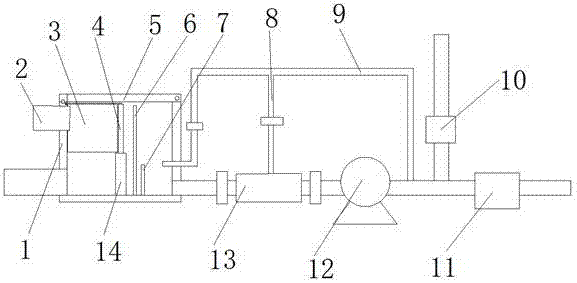
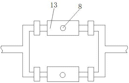
[0015] refer to Figure 1-2 , a high-efficiency treatment and discharge device for petrochemical sewage, including a pre-discharge pool 1, a water inlet pipe 2 is connected to the top of one side of the pre-discharge pool 1 through a flange, and a baffle plate 14 is welded in the middle of the inner wall of the bottom of the pre-discharge pool 1, and the baffle plate 14 Both ends of the top are welded with clamping rails, and a filter plate 4 is inserted between the two clamping rails. The top of the inner wall of the pre-drainage pool 1 near the water inlet pipe 2 is provided with a clamping groove, and a filter is clamped in the clamping groove. Net cage 3, the two...


PUM


Abstract

The invention discloses a high-efficiency treatment and discharge device for petrochemical sewage, which includes a pre-discharge pool, the top of one side of the pre-discharge pool is connected to a water inlet pipe through a flange, and a baffle plate is welded in the middle of the inner wall of the bottom of the pre-discharge pool. Both ends of the top of the baffle are welded with clamping rails, and a filter plate is inserted between the two clamping rails, and a clamping groove is opened on the top of the inner wall of the pre-discharging pool near the water inlet pipe. In the present invention, the sewage treated by the third stage flows into the pre-discharge pool, passes through the filter net box and the filter screen plate, and then monitors the water quality in real time through the water quality monitor. The qualified sewage is directly discharged through the drainage pump or reused in production, and the unqualified The sewage is recovered and treated through the recovery pipe, and the filter screen inside the filter is washed by the flushing pipe in real time, which can effectively reduce the number of dismantling and inspections. Two filters installed in parallel, one for standby and one for use, can effectively avoid frequent shutdown of the drainage pump. To achieve the effect of efficient discharge of petrochemical sewage.

Description

technical field [0001] The invention relates to the technical field of petrochemical sewage discharge, in particular to a high-efficiency treatment and discharge device for petrochemical sewage. Background technique [0002] Petrochemical sewage is the sewage produced by petrochemical production, such as synthetic rubber and synthetic plastics, fibers, detergents and other products, as well as sewage discharged from the production process of chemical raw materials such as benzene, naphthalene, methanol, glycerin, acetaldehyde, etc., after three-stage treatment The treated sewage can meet the requirements of higher environmental sanitation standards and be directly discharged or reused in production. However, the existing treated sewage discharge device has a simple structure, and most of them are discharged directly through pipelines connected to the sewage outlet without control and monitoring. There will often be phenomena that do not meet the standards. Re-containment and...

Claims


Application Information

Patent Timeline
Patent Type & Authority Applications(China)
IPC IPC(8): C02F1/00B01D29/01B01D29/64B01D29/50C02F103/36
Inventor 周忠太张齐亮孟红文张小涛
Owner 新乡市巨能合成材料有限公司
Why Eureka
Eureka Blog
Learn More