Bus bar welding equipment
A technology for welding equipment and bus bars, applied in welding equipment, welding equipment, auxiliary welding equipment, etc., can solve the problems of reducing battery production efficiency, reducing production efficiency, safety issues, and work intensity, so as to improve overall work efficiency and automation level Improved effect
- Summary
- Abstract
- Description
- Claims
- Application Information
AI Technical Summary
Problems solved by technology
Method used
Image

Examples
no. 1 example
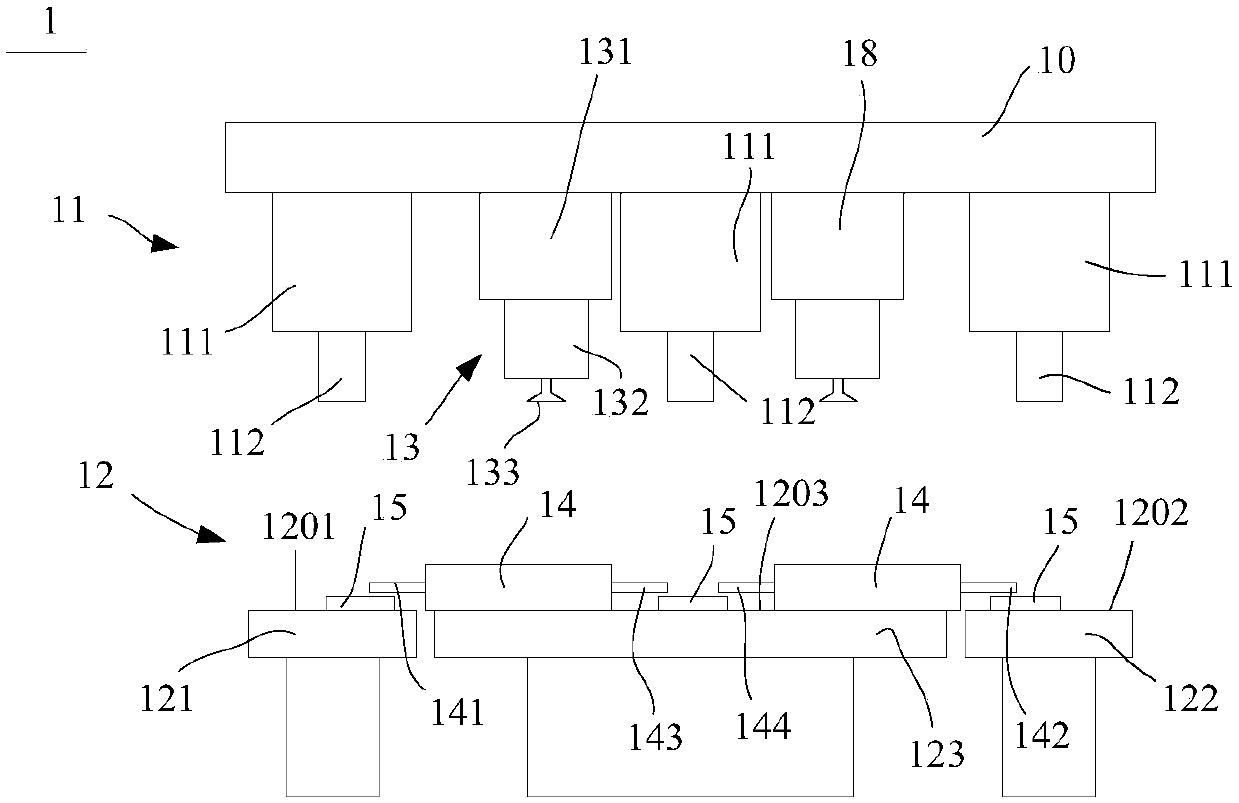
[0031] figure 1 is a structural schematic diagram of the bus bar welding equipment of the present invention shown in the first exemplary embodiment.
[0032] Such as figure 1 As shown, the bus bar welding equipment 1 of this embodiment includes a welding device 11 , a carrying device 12 and a bus bar fetching device 13 . Among them, the welding device 11 is used to weld the bus bar 15 to the battery string 14 , the carrying device 12 is used to carry the battery string 14 and the bus bar 15 , and the bus bar fetching device 13 is used to pick up and send the bus bar 15 .
[0033] In this embodiment, there are three sets of welding devices 11 , all of which are installed on the bracket 10 respectively. Each welding device 11 can include a telescopic structure 111 and a welding head 112, wherein the telescopic structure 111 can be movably or fixedly installed on the support 10, and the other end is equipped with a welding head 112, so that the welding head 112 can move up and ...
no. 2 example
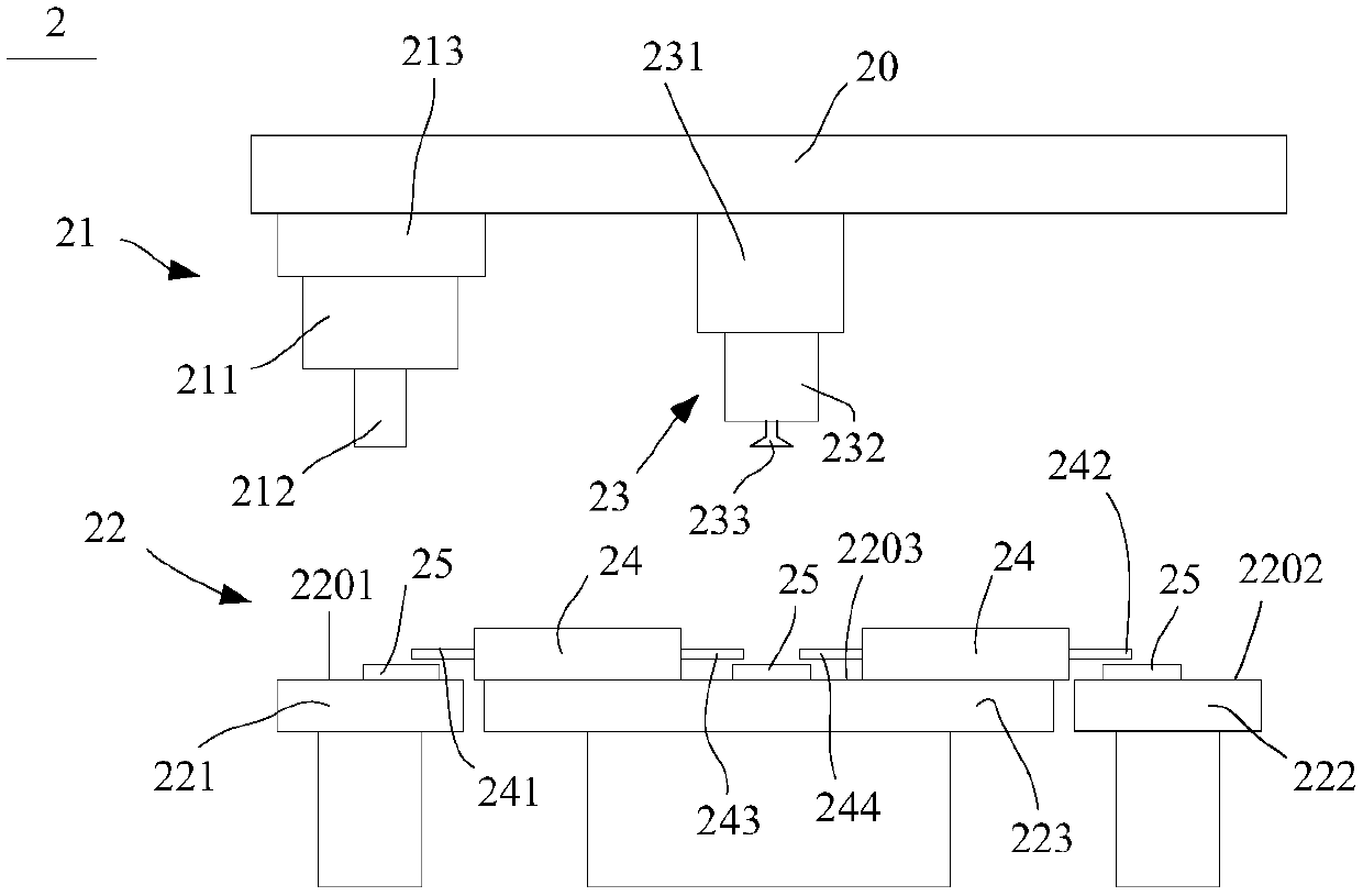
[0040] figure 2 is a structural schematic diagram of the bus bar welding equipment of the present invention shown in the second exemplary embodiment.
[0041] Such as figure 2 As shown, the bus bar welding equipment 2 of this embodiment includes a welding device 21 , a carrying device 22 and a bus bar fetching device 23 . The structure of the welding device 21, the carrying device 22 and the bus bar pick-up device 23 is basically the same as that of the first embodiment. For the specific structure, refer to the statement of the first embodiment and please refer to the attached figure 2 Understand, no further explanation here.
[0042] Compared with the first embodiment, in this embodiment, there is only one welding device 21, and a traversing structure 213 is added in the welding device 21, and the telescopic structure 211 is installed on the support 20 through the traversing structure 213, and the traversing structure 213 is based on According to welding requirements, i...
no. 3 example
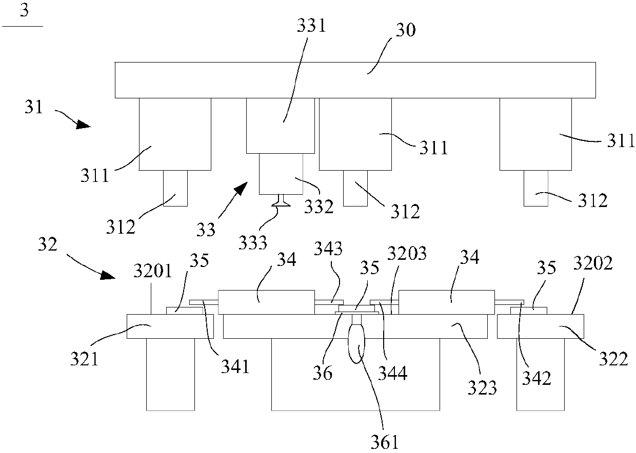
[0045] image 3 is a structural schematic diagram of the bus bar welding equipment of the present invention shown in the third exemplary embodiment.
[0046] Such as image 3 As shown, the bus bar welding equipment 3 of this embodiment includes a welding device 31 , a carrying device 32 and a bus bar fetching device 33 . The structure of the welding device 31, the carrying device 32 and the bus bar pick-up and delivery device 33 is basically the same as that of the first embodiment and the second embodiment. For the specific structure, refer to the statement of the first embodiment and the second embodiment and please refer to the attached image 3 Understand, no further explanation here.
[0047] Compared with the first embodiment and the second embodiment, in this embodiment, a heat insulating bar 36 is added on the third bearing surface 3203, and the bus bar 35 is arranged on the heat insulating bar 36, thereby reducing the welding device 31 on the heat insulating bar 36....
PUM
 Abstract
Description
Claims
Application Information
 - R&D
- Intellectual Property
- Life Sciences
- Materials
- Tech Scout
- Unparalleled Data Quality
- Higher Quality Content
- 60% Fewer Hallucinations
Browse by: Latest US Patents, China's latest patents, Technical Efficacy Thesaurus, Application Domain, Technology Topic, Popular Technical Reports.
© 2025 PatSnap. All rights reserved.Legal|Privacy policy|Modern Slavery Act Transparency Statement|Sitemap|About US| Contact US: help@patsnap.com