Bicycle with swing arm device

A technology for bicycles and bicycle racks, which is applied to chain/belt transmissions, vehicle components, vehicle gearboxes, etc., can solve the problems of power loss, loss, and cyclist's riding effort, so as to reduce power loss and increase transmission force. Efficiency, simple and reasonable structure

Active Publication Date: 2018-01-09
吴监玉
View PDF5 Cites 5 Cited by
  • Summary
  • Abstract
  • Description
  • Claims
  • Application Information

AI Technical Summary

Problems solved by technology

The development of bicycles has a long history and has developed rapidly. Since the birth of the first bicycle, bicycles have always used double pedals to rotate the sprocket with a pair of reverse bell cranks. It is transformed into rotational torque, which is transmitted to the flywheel through the chain, and in the way of driving the rear wheel of the bicycle forward. In this way, the force transmission efficiency depends on the torque generated by the crank, the magnitude of the pedaling force, the direction of force and the direction of the crank. Angle of force, people will produce a lot of force loss when riding
[0003] In addition, with this kind of driving device, the rider's legs and feet must do circular motions. During the riding process, the pedals cannot always maintain the state of transmitting force. The driving effect will cause a lot of power loss, especially when riding uphill, the rider will be more strenuous when riding, and this defect of the existing crank type bicycle is more prominent

Method used


Image

  • Bicycle with swing arm device
  • Bicycle with swing arm device
  • Bicycle with swing arm device

Examples


Embodiment 1

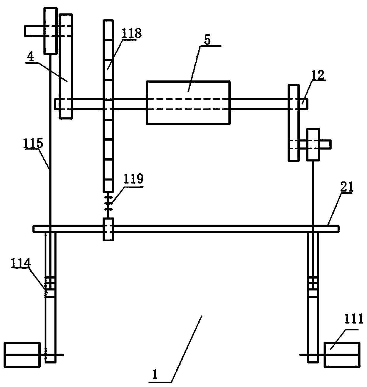
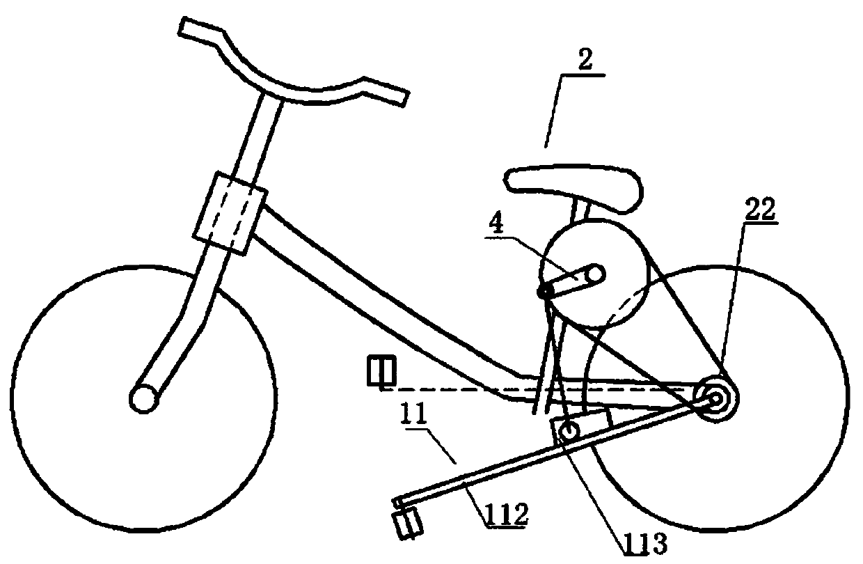
[0032] Such as figure 1 and figure 2 Shown, the present invention relates to a kind of bicycle with swing arm device, and it comprises swing arm device 1, bicycle 2, flywheel axle 21, flywheel 22, bell crank 4 and axle sleeve 5, swing arm device 1 comprises power transmission device 11 And connecting shaft 12, power transmission device 11 comprises pedal 111, rocker arm lever 112, pulley 113, pulley groove 114, connecting rod 115, chainring 118 and chain 119, rocker arm lever 112 one end is screwed pedal 111, and the other end is connected with fly The wheel shaft 21 is connected, the pedal 111 can apply the active force to the bicycle to move forward, and transmit the active force to the rocker lever 112, the rocker lever 112 can rotate around the flywheel shaft 21, and the rocker lever 112 is fixedly connected with a pulley groove 114, The pulley groove 114 is rectangular, and the pulley 113 moves in the pulley groove 114. The pulley 113 can reduce the friction between the...

Embodiment 2

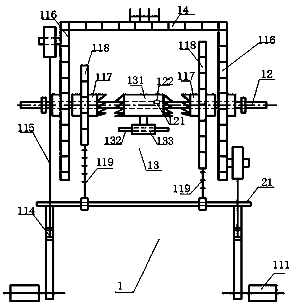
[0034] Such as image 3 , Figure 4 , Figure 5 and Figure 6Shown, the technical scheme that present embodiment provides is the same as embodiment 1, and its difference is that the bicycle with swing arm device comprises swing arm device 1 and bicycle 2, and swing arm device 1 is installed on the bicycle frame; It includes a power transmission device 11, a connecting shaft 12 and a shifting device 13. The power transmission device 11 is symmetrically arranged on both sides of the bicycle 2, and the two are connected by the connecting shaft 12. The power transmission device 11 can generate and transmit power to drive the bicycle forward. The connecting shaft 12 is installed under the vehicle seat, the middle part of the connecting shaft 12 is provided with a keyway 121, and the keyway 121 is provided with a flat key 122. The connecting shaft 12 is fixed by the fixing frame 3, and the fixing frame 3 is a rectangle with one side opening, and the fixing frame 3 is parallel. Th...

Embodiment 3

[0039] Such as Figure 5 As shown, the difference between the technical solution provided by this embodiment and that of Embodiment 1 is that in the technical solution implemented in this embodiment, the pulley groove 114 is movably connected to the rocker lever 112, and the lower end of the pulley groove 114 is provided with a fixed The sleeve 1141, the fixed sleeve 1141 is provided with an adjustment opening, and the two edges of the adjustment opening are symmetrically provided with a bearing piece 1142 that can be loaded with a fastening device. There is a gap between the two bearing pieces 1142. On the two bearing pieces 1142 Two symmetrical mounting holes 1143 are provided, and the adjusting screw passes through the mounting holes 1143 and cooperates with the nut to tighten the two bearing pieces 1142 so that the two bearing pieces 1142 are closely attached.

[0040] The advantage of this arrangement is that the user can adjust the pulley groove 114 according to his own ...


PUM


Abstract

The invention relates to a bicycle with a swing arm device. The bicycle comprises the swing arm device and a bicycle frame. The swing arm device is mounted on the bicycle frame and comprises power transmission devices symmetrically arranged on the two sides of a bicycle body. Each power transmission device comprises a swing arm lever, a pulley groove, a pulley, a connecting rod and a crankset. Oneends of the swing arm levers are connected with pedals, and the other ends of the swing arm levers are connected with a flywheel shaft. The pulley grooves are formed in the swing arm levers. The pulleys make movement in the pulley grooves. One ends of the connecting rods are connected with the pulleys, and the other ends of the connecting rods are connected with a crank throw. The crank throw andthe cranksets are mounted on a connecting shaft. The cranksets and a flywheel transmit power through chains. The structure is simple; by stepping the pedals up and down, the pulleys make linear movement in the pulley grooves, the connecting rods drive the crank throw to drive the cranksets to make circular movement, and thus the power is transmitted through the chains to enable the bicycle to advance; and the structure is simple and reasonable, an original crank throw type bicycle structure is changed, thus much labor is saved during riding, and the force transmission efficiency is improved.

Description

technical field [0001] The invention relates to a bicycle, especially a bicycle with a swing arm device. Background technique [0002] At present, the global climate is warming, and more and more people choose green travel, and bicycles have become the preferred means of transportation for people to travel green. The development of bicycles has a long history and has developed rapidly. Since the birth of the first bicycle, bicycles have always used double pedals to rotate the sprocket with a pair of reverse bell cranks. It is transformed into rotational torque, which is transmitted to the flywheel through the chain, and in the way of driving the rear wheel of the bicycle forward. In this way, the force transmission efficiency depends on the torque generated by the crank, the magnitude of the pedaling force, the direction of force and the direction of the crank. The angle of force, people will produce a lot of force loss when riding. [0003] In addition, with this kind of ...

Claims


Application Information

Patent Timeline
Patent Type & Authority Applications(China)
IPC IPC(8): B62M1/28B62M9/10
Inventor 吴监玉
Owner 吴监玉
Why Eureka
Try Eureka