Dynamic pellet roaster and using method thereof

A technology of roasting furnace and pelletizing, applied in the field of pelletizing, can solve the problems of difficulty in discharging, less roasting amount of pellets, and excessively rapid decrease of furnace temperature, so as to solve the problem of difficult reclaiming, large roasting amount, and simple and easy method. Effect

Inactive Publication Date: 2018-01-09
ANGANG STEEL CO LTD
View PDF8 Cites 2 Cited by
  • Summary
  • Abstract
  • Description
  • Claims
  • Application Information

AI Technical Summary

Problems solved by technology

[0002] It has always been a difficult problem for metallurgists to use electric furnace to simulate pellet roasting in the laboratory. The main difficulties are that, first, the amount of pellet roasting is small, the roasting time is long, and the roasting is uneven; the second is that static non-blast roasting cannot Simulate the actual situation on site
The former is because the heating of the pellets belongs to radiation conduction heat transfer, the roasting speed is slow, and the amount of charging materials should not be too much at one time, otherwise the experiment time will be too long, and the pellets on the surface of the crucible and inside the roasting and oxidation atmosphere are different, resulting in a large quality difference. In addition, the volume of the pellets expands during the roasting process. If the loading is too much, they will be squeezed and the discharge will be difficult.
The surface of the existing experimental furnace manufacturing and use, in the heating process of the electric furnace, if the wind speed is too fast and the air volume is too large, the furnace temperature will drop too fast, which cannot meet the temperature requirements for pellet roasting

Method used


Image

  • Dynamic pellet roaster and using method thereof
  • Dynamic pellet roaster and using method thereof
  • Dynamic pellet roaster and using method thereof

Examples


Embodiment Construction

[0016] The following describes in conjunction with specific embodiments:

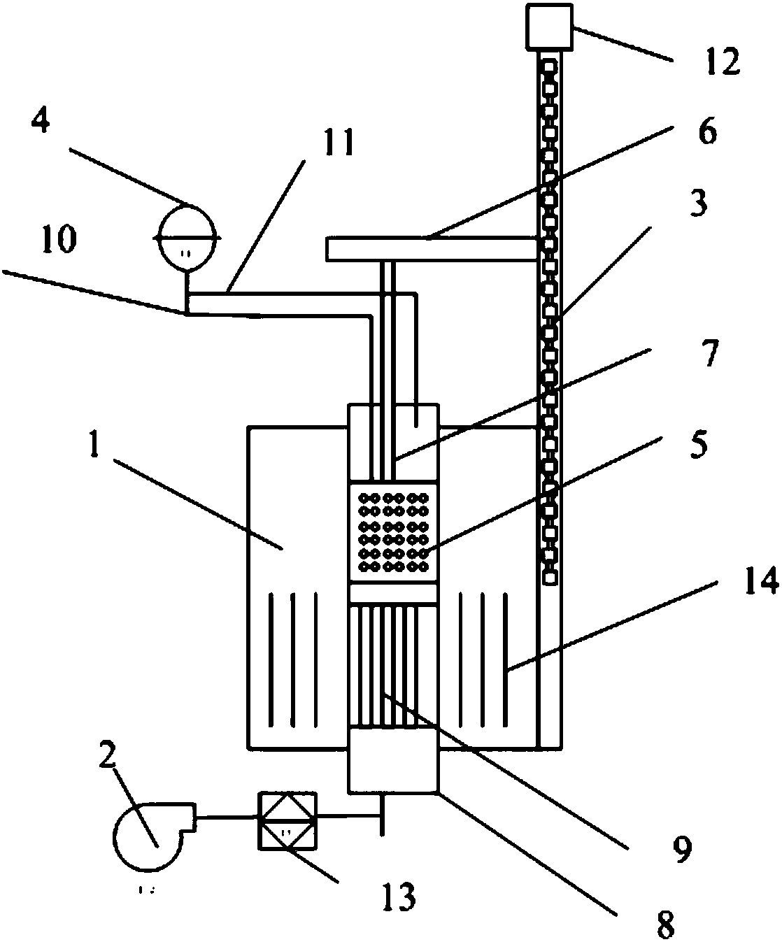
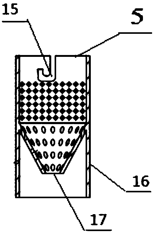
[0017] Including the roaster body 1, the air supply pump 2, the drive screw 3, the computer real-time monitoring and control system 4, and the material cage 5. The drive screw 3 driven by the motor 12 and the material cage 5 containing the pellets pass through the upper bracket 6 and The supporting rods 7 are connected and can move up and down into the furnace 8 in the roasting furnace body 1; the heating element 14 is located at the lower part of the roasting furnace body 1, and its height does not exceed 2 / 3 of the size of the entire furnace 8. The heating element 14 is located around the furnace 8 And evenly distributed; the bottom of the furnace 8 is provided with a porous heat storage brick 9 or a high aluminum ball with a diameter of 4mm-20mm, and the upper edge is not higher than 1 / 2 of the height of the heating element 14; the shape of the basket 5 is a lower cone, And there is a hole with a diamet...


PUM

PropertyMeasurementUnit
diameteraaaaaaaaaa
diameteraaaaaaaaaa

Abstract

The invention discloses a dynamic pellet roaster which comprises a roaster body, an air feeding air pump, a transmission lead screw, a computer real-time monitoring and controlling system and a material cage. The transmission lead screw driven by a motor is connected with the material cage filled with pellets through an upper support and a supporting rod, and the transmission lead screw can move up and down and enter a hearth in the roaster body. Heating elements are located on the lower portion of the roaster body, located on the periphery of the hearth and evenly distributed, and the heightof the heating elements is not larger than 2 / 3 of the dimension of the whole hearth. Porous heat storage bricks or high-aluminum balls with the diameter being 4-20 mm are arranged at the bottom insidethe hearth, and the upper edges of the porous heat storage bricks or the high-aluminum balls are not higher than the 1 / 2 positions of the heating elements. The material cage is in a downward conicalshape, a hole with the diameter being 10-12 mm is formed in the middle of the bottom of the material cage, and small holes with the diameter being smaller than 10 mm are evenly distributed in the sidewall of the material cage. Cold air blown from the air feeding air pump passes through a flowmeter and then enters the hearth from the bottom, the upper edge of the interior of the material cage andthe upper edge of the hearth are provided with a thermocouple and a smoke composition collecting system correspondingly, a collected temperature signal and a collected smoke composition signal are transmitted to the computer real-time monitoring and controlling system, and meanwhile, the computer real-time monitoring and controlling system can control the motor and the flowmeter according to the signals.

Description

Technical field [0001] The invention belongs to the technical field of pellets, and particularly relates to a pellet dynamic roaster and a method of use thereof. Background technique [0002] The use of electric furnaces to simulate pellet roasting in the laboratory has always been a problem for metallurgists. The main difficulties are that the first is that the amount of pellets is small, the roasting time is long, and the roasting is uneven. The second is that static non-blast roasting cannot Simulate the actual situation on site. The former is because the pellet heating is radiative conduction heat transfer, the roasting speed is slow, and the amount of charge can not be large at one time, otherwise the experiment time will be too long, and the pellets on the surface of the crucible and the inside of the pellet will be roasted and oxidized differently, resulting in a great quality. In addition, the volume of the pellets expands during the roasting process. If the amount is to...

Claims


Application Information

Patent Timeline
Patent Type & Authority Applications(China)
IPC IPC(8): C22B1/02
Inventor 任伟张立国李金莲张伟韩子文王亮孙鹏王再义张宇童晓宇
Owner ANGANG STEEL CO LTD
Why Eureka
Try Eureka