
Flame-retardant type anti-explosion valve of crankcase

An explosion-proof valve, crankcase technology, applied in the direction of engine components, machines/engines, mechanical equipment, etc., can solve the problems of unfavorable pressure reduction and flame suppression, large load of explosion-proof valves, etc., to improve flame suppression and pressure reduction effect, production The effect of high efficiency and improved utilization

Active Publication Date: 2018-01-09
ZHEJIANG UNIV OF TECH
View PDF6 Cites 1 Cited by
  • Summary
  • Abstract
  • Description
  • Claims
  • Application Information

AI Technical Summary

Problems solved by technology

The upper and lower penetration of the flame-retardant sheet will easily cause part of the high-temperature and high-pressure air to rush to the upper part of the explosion-proof valve, resulting in excessive load on the upper part of the explosion-proof valve, which is not conducive to reducing pressure and extinguishing the flame

Method used


Image

  • Flame-retardant type anti-explosion valve of crankcase
  • Flame-retardant type anti-explosion valve of crankcase
  • Flame-retardant type anti-explosion valve of crankcase

Examples


Embodiment Construction

[0027] Below in conjunction with accompanying drawing, the present invention is further described as follows:

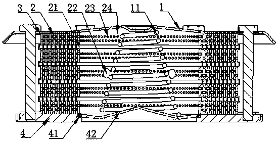
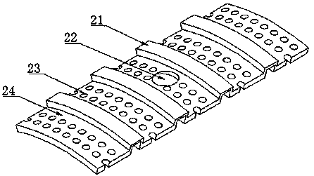
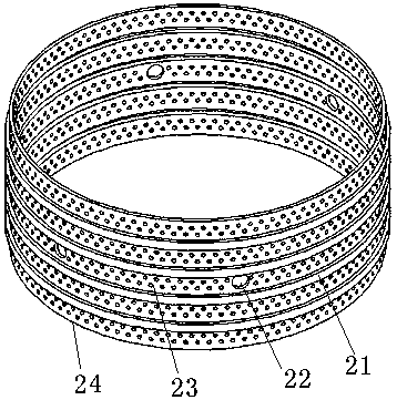
[0028] Such as Figure 1-4 As shown, the crankcase flame-retardant explosion-proof valve of the present invention includes a valve cover 1 and a valve seat 4 with a disc 42. The lower surface of the top end of the valve cover 1 is provided with a protrusion, and one end of the spring 11 is fixed. On the protrusion on the lower surface of the valve cover 1, the other end of the spring 11 is pressed against the disc 42 of the valve seat 4, and the valve disc 42 and the valve seat 4 are sealed by a sealing ring 41. , a flame retardant is installed between the valve seat 4 and the valve cover 1, and the flame retardant includes several inner flame retardant rings 2 and an outer flame retardant ring 3, and the outer flame retardant ring 3 It includes the outer flame retardant ring body and the installation ring 31 arranged at the upper and lower ends of the outer flame r...


PUM


Abstract

The invention discloses a flame-retardant type anti-explosion valve of a crankcase. The flame-retardant type anti-explosion valve of a crankcase comprises a valve deck and a valve seat. A valve clackis arranged on the valve seat. An inner flame-retardant ring group, an outer flame-retardant ring and a spring are arranged between the valve deck and the valve seat. The upper end of the spring is fixed to the valve deck. The lower end of the spring tightly presses the valve clack. The inner flame-retardant ring group and the outer flame-retardant ring are arranged in the space formed by the valve deck and the valve seat to form a flame retardant device. Because the flame-retardant type anti-explosion valve of a crankcase is adopted, the airflow through holes of the valve are evenly distributed along the surfaces of ring bodies, the airflow through holes of the same ring body are evenly arranged side by side, the airflow through holes of two adjacent ring bodies stagger to form labyrinthtype bend channels, the time for airflow and flames to pass through can be effectively prolonged while heat exchange between airflow and the inner walls of the flame retardant rings can be sufficient,the use ratio of the flame retardant rings is increased to the maximum degree, the temperature is lowered, and the purposes of reducing pressure and putting out flames are achieved finally. The flame-retardant type anti-explosion valve of a crankcase is simple in structure, and easy to produce and install. The problems exist in an anti-explosion valve can be solved. The flame-retardant type anti-explosion valve of a crankcase has broad application prospects.

Description

technical field [0001] The invention belongs to the technical field of mechanical products, and in particular relates to a crankcase flame-retardant explosion-proof valve. Background technique [0002] When the internal combustion engine is running, heat will be generated in the crankcase due to the movement of the crankshaft, connecting rod and piston, etc. When the internal combustion engine fails, the temperature and pressure in the crankcase will rise sharply, causing deflagration of oil and gas, thus generating high-pressure airflow And high-temperature flames, and the explosion-proof valve is arranged on the box body of the crankcase, which can achieve the purpose of releasing pressure, lowering the temperature and extinguishing the flame. While releasing the pressure, it can prevent the flame from passing through and then close to prevent the air from entering, maintain a sealed state, and prevent the external air from entering and mixing with high-temperature oil mis...

Claims


Application Information

Patent Timeline
Patent Type & Authority Applications(China)
IPC IPC(8): F02B77/10
Inventor 刘红沈施佳蒋兰芳沈少祥
Owner ZHEJIANG UNIV OF TECH
Learn More