Horizontal drying kiln structure
A drying kiln and horizontal technology, which is applied in the field of horizontal drying kiln structure, can solve the problems of inability to increase the amount of material input, the moisture content of the material is not up to standard, and the physical damage rate is high, so as to ensure drying efficiency and improve drying efficiency. , to ensure the effect of full contact
- Summary
- Abstract
- Description
- Claims
- Application Information
AI Technical Summary
Problems solved by technology
Method used
Image

Examples
Embodiment Construction
[0029] Embodiments of the technical solutions of the present invention will be described in detail below in conjunction with the accompanying drawings. The following examples are only used to illustrate the technical solutions of the present invention more clearly, and therefore are only examples, rather than limiting the protection scope of this patent.
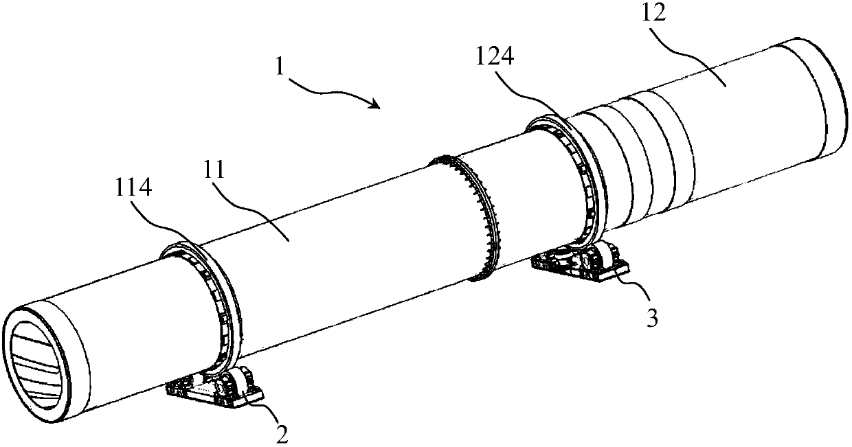
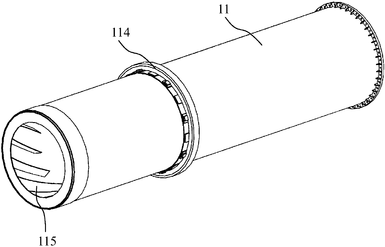
[0030] Such as Figure 1 to Figure 9 As shown, the present invention discloses a horizontal drying kiln structure, including a rotary kiln shell 1; the rotary kiln shell 1 includes a feed rotary shell 11 and a discharge rotary shell 12, and The discharge end is connected with the feed end of the discharge rotary cylinder 12 by bolts.
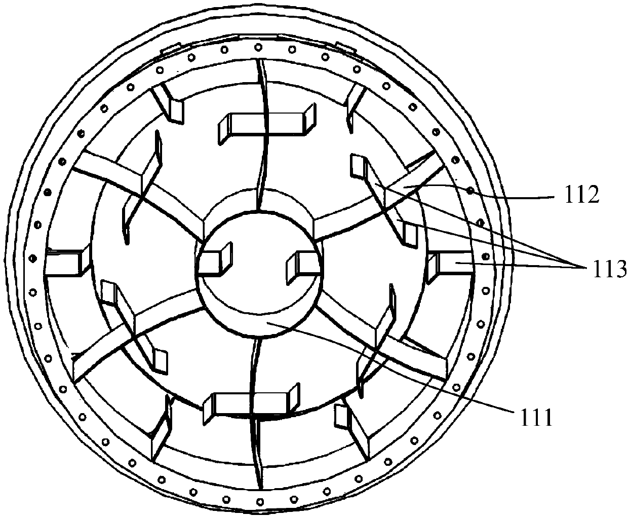
[0031]The middle part of the feeding rotating cylinder 11 is provided with a feeding central cylinder 111 concentric with the central axis, and a plurality of feeding separating plates 112 are evenly arranged between the inner wall of the feeding rotating cylinder 11 and the feeding central c...
PUM
 Abstract
Description
Claims
Application Information
 - R&D
- Intellectual Property
- Life Sciences
- Materials
- Tech Scout
- Unparalleled Data Quality
- Higher Quality Content
- 60% Fewer Hallucinations
Browse by: Latest US Patents, China's latest patents, Technical Efficacy Thesaurus, Application Domain, Technology Topic, Popular Technical Reports.
© 2025 PatSnap. All rights reserved.Legal|Privacy policy|Modern Slavery Act Transparency Statement|Sitemap|About US| Contact US: help@patsnap.com