
Large-area microchannel plate type photomultiplier test device

A technology of photomultiplier tubes and microchannel plates, which is applied in the directions of measuring devices, testing optical properties, and measuring electricity, can solve the problem of inability to realize batch testing of large-size photomultiplier tubes, inability to accurately test large-size photomultiplier tubes, and inability to perform well Testing the overall performance of large-size photomultiplier tubes and other issues

Active Publication Date: 2018-01-09
NORTH NIGHT VISION TECH +1
View PDF4 Cites 17 Cited by
  • Summary
  • Abstract
  • Description
  • Claims
  • Application Information

AI Technical Summary

Problems solved by technology

[0005] The purpose of the present invention is to provide a large-area microchannel plate-type photomultiplier tube testing device, which solves the problem that the traditional photomultiplier tube testing device cannot test the overall performance of large-scale photomultiplier tubes well, and cannot accurately test large-scale photomultiplier tubes due to the influence of the geomagnetic field. Large-scale photomultiplier tubes, limited test space cannot realize batch testing of large-size photomultiplier tubes

Method used


Image

  • Large-area microchannel plate type photomultiplier test device
  • Large-area microchannel plate type photomultiplier test device
  • Large-area microchannel plate type photomultiplier test device

Examples


Embodiment Construction

[0047] In order to better understand the technical content of the present invention, specific embodiments are given together with the attached drawings for description as follows.

[0048] Aspects of the invention are described in this disclosure with reference to the accompanying drawings, which show a number of illustrated embodiments. Embodiments of the present disclosure are not necessarily intended to include all aspects of the invention. It should be appreciated that the various concepts and embodiments described above, as well as those described in more detail below, can be implemented in any of numerous ways, since the concepts and embodiments disclosed herein are not limited to any implementation. In addition, some aspects of the present disclosure may be used alone or in any suitable combination with other aspects of the present disclosure.

[0049] to combine figure 1 , a large-scale photomultiplier tube batch testing device, including a light source system, an e...


PUM

PropertyMeasurementUnit
Lengthaaaaaaaaaa
Apertureaaaaaaaaaa

Abstract

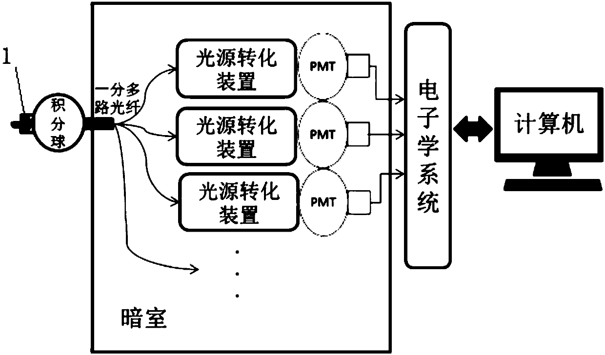
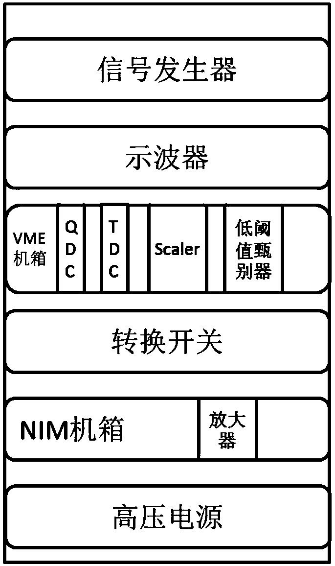
The present invention provides a large-area microchannel plate type photomultiplier testing device. The device includes a light source system, an electronic system, a darkroom and a computer; the light source system uniformly transmits light emitted by a light source to a plurality of light source conversion devices through an integrating sphere and a one-to-many optical fiber; the light source conversion devices receive the point light source of the optical fiber and outputs uniform surface light sources; and each surface light source illuminates the total cathode surfaces of one large-size photomultiplier. According to the large-area microchannel plate type photomultiplier tube testing device of the invention, the overall performance of a plurality of large-area photomultipliers can be simultaneously tested on the basis of the electronic system and computer test software. With the large-area microchannel plate type photomultiplier testing device adopted, the batch test work of the overall performance of the large-size photomultipliers can be well completed, the compliance of the test environment and use environment of the large-size photomultipliers can be improved, the batch test efficiency of the large-size photomultipliers can be improved, the limitations of a point light source test system are eliminated, and the problem of low efficiency of a point-source scanning test system can be solved.

Description

technical field [0001] The invention relates to the technical field of photomultiplier tubes, in particular to a large-area microchannel plate type photomultiplier tube testing device. Background technique [0002] A photomultiplier tube is a vacuum device that converts weak optical signals into electrical signals. It is widely used in optical analysis instruments, medical instruments, oil logging, space exploration, high-energy physics, laser applications and other fields. It involves many industries in the national economy, especially the application of important projects such as "Shenzhou Spaceship", "Shenguang III", "Ultraviolet Communication", "Small Warhead", "052 Missile Destroyer", and neutrino detection. [0003] With the increase of neutrino detection experiments, the demand for large-scale photomultiplier tubes is increasing, especially for 20-inch photomultiplier tubes. For the Jiangmen neutrino detection experiment led by the Institute of High Energy Physics, C...

Claims


Application Information

Patent Timeline
IPC IPC(8): G01M11/02G01R31/00
Inventor 黄国瑞钱森司曙光孙建宁刘术林李珅金真李冬任玲邵爱飞胡松曹宜起
Owner NORTH NIGHT VISION TECH
Learn More