Nuclear magnetic resonance method for obtaining rock permeability profile
A technology of nuclear magnetic resonance and permeability, which is applied in the direction of permeability/surface area analysis, analysis by nuclear magnetic resonance, and measurement devices, which can solve the problems of difficult internal fluid flow and low permeability, and achieve the effect of improving the evaluation effect
- Summary
- Abstract
- Description
- Claims
- Application Information
AI Technical Summary
Problems solved by technology
Method used
Image

Examples
Embodiment 1
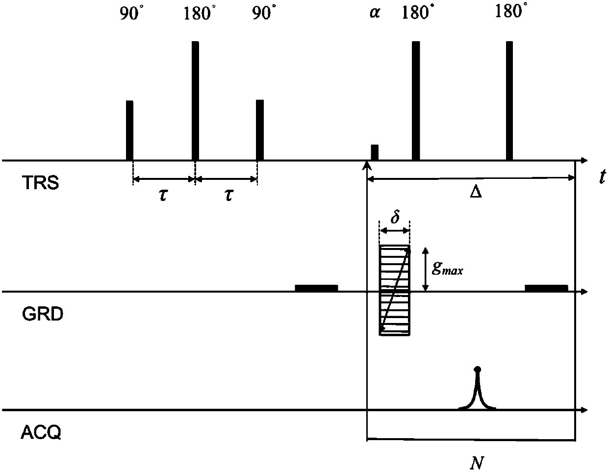
[0054] Regarding the novel nuclear magnetic resonance weighted imaging technology involved in this invention, such as figure 1 Shown, it is characterized in that, described method comprises:
[0055] Step 1. Apply a 90° radio frequency pulse to the hydrogen-containing proton spin system of the tested sample on the TRS channel to convert the macroscopic magnetization vector M 0 Turn to horizontal plane;
[0056] Step 2. After waiting for a very short time T, apply a 180° radio frequency pulse to the spin system on the TRS channel to regroup the transverse plane magnetization vector after dephasing; the very short time T is usually tens of microseconds .
[0057] Step 3, after waiting for a very short time T again, apply a 90° radio frequency pulse to the spin system on the TRS channel, and turn the reunited transverse plane magnetization vector by 90° to the vertical axis (in line with the static magnetic field in the same direction);
[0058] Step 4, applying a gradient pu...
Embodiment 2
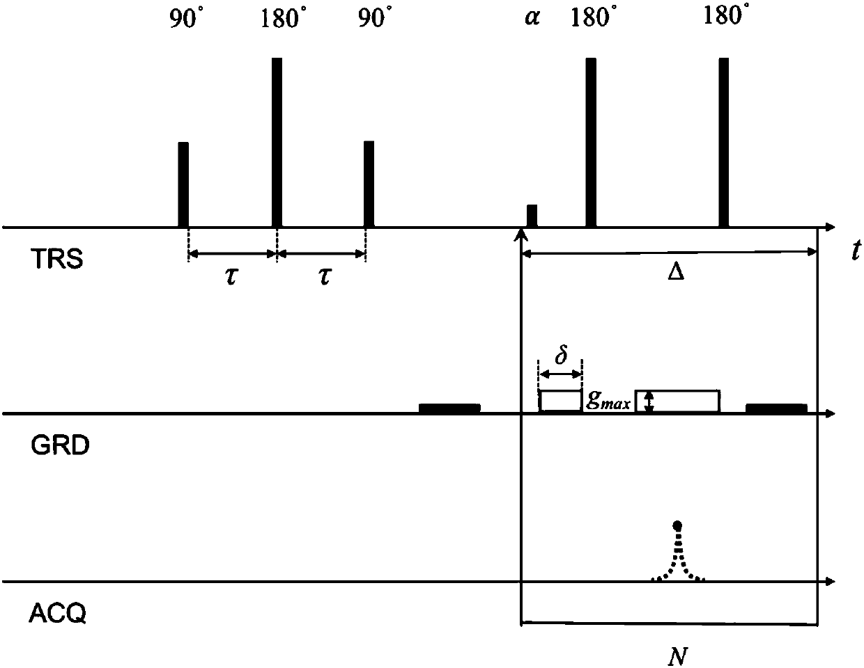
[0078] On the basis of the first embodiment, the data acquisition method can be replaced by another implementation form, and other steps remain unchanged, and the pulse sequence diagram is as follows figure 2 As shown, the method includes:
[0079] Step 1. Apply a 90° radio frequency pulse to the hydrogen-containing proton spin system of the tested sample on the TRS channel to convert the macroscopic magnetization vector M 0 Turn to horizontal plane;
[0080] Step 2. After waiting for a very short time T, apply a 180° radio frequency pulse to the spin system of the sample under test on the TRS channel to re-gather the transverse plane magnetization vector after dephasing; the very short time T is usually tens of microseconds ;
[0081] Step 3. After waiting for a very short time T again, apply a 90° pulse to the spin system of the tested sample on the TRS channel, and turn the reunited transverse plane magnetization vector by 90° to the longitudinal axis (in line with the d...
Embodiment 3
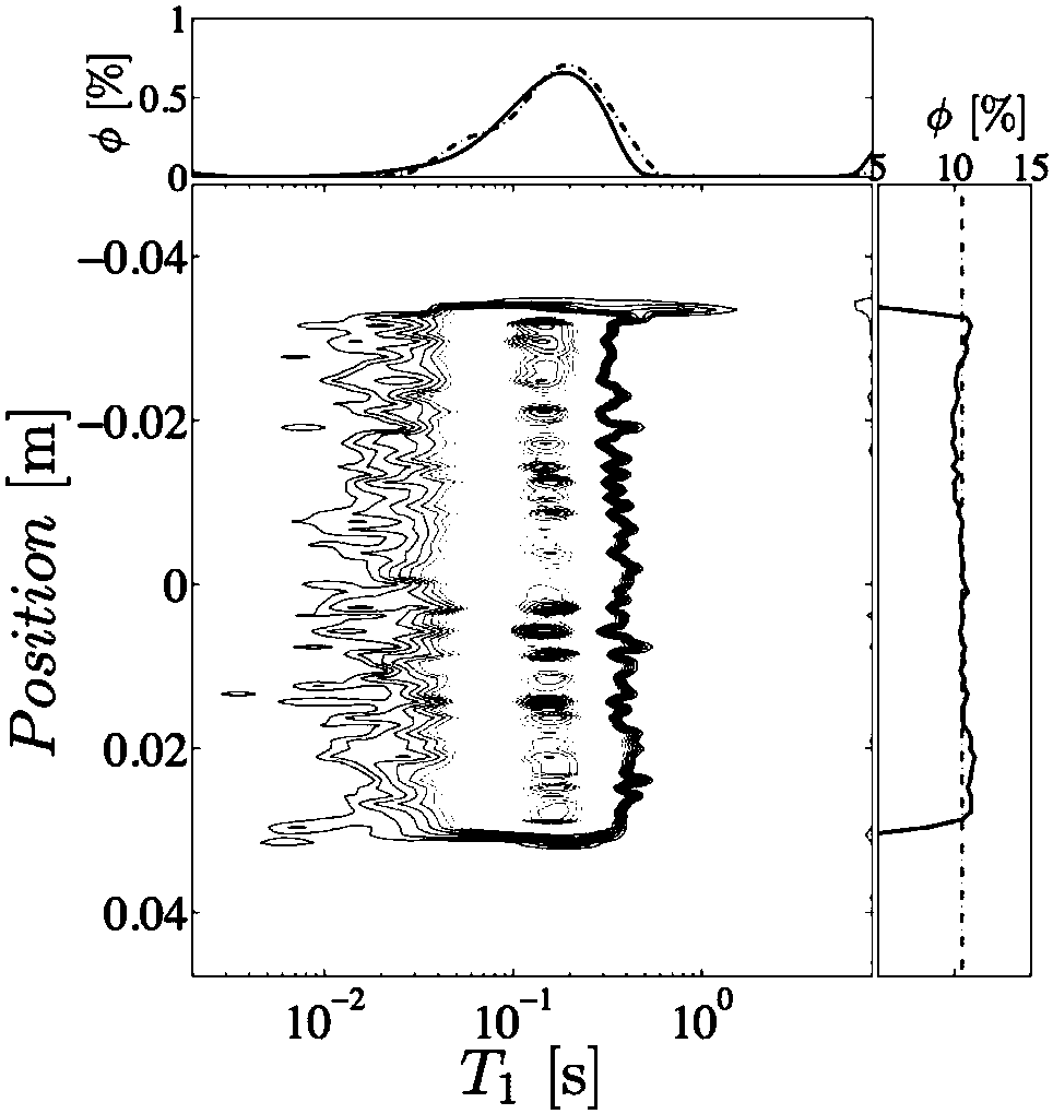
[0088] On the basis of Embodiments 1 to 2, regarding the method for defining the local connectivity factor of the rock core involved in this invention, as Figure 4 As shown, it is characterized in that it can pass through the T of the adjacent layer 1 The degree of coupling of the distribution function is defined. This definition is based on a reasonable assumption that if the T 1 The higher the coupling degree of the distribution function, the better the pore connectivity in this local area and the higher the rock permeability; and vice versa. Therefore, the definition method of the local connectivity factor is as follows:
[0089]
[0090] Among them, p i,i+1 is the connectivity factor between the i-th layer rock and the i+1-th layer rock; represents the j-th T in the i-th layer of rock 1 Amplitude values corresponding to the distribution; abcd represent the adjacent layers T 1 Interval values of the AND logic operation and the Union logic operation of the dis...
PUM
 Abstract
Description
Claims
Application Information
 - R&D
- Intellectual Property
- Life Sciences
- Materials
- Tech Scout
- Unparalleled Data Quality
- Higher Quality Content
- 60% Fewer Hallucinations
Browse by: Latest US Patents, China's latest patents, Technical Efficacy Thesaurus, Application Domain, Technology Topic, Popular Technical Reports.
© 2025 PatSnap. All rights reserved.Legal|Privacy policy|Modern Slavery Act Transparency Statement|Sitemap|About US| Contact US: help@patsnap.com