
A current detection circuit for pwm/pfm dual mode dc-dc switching power supply

A technology of current detection circuit and switching power supply, which is applied in the direction of measuring current/voltage, circuit breaker testing, measuring devices, etc. It can solve the problems of reverse current of the lower switching tube, wrong mode switching, and limited detection accuracy, etc., to achieve Ensure pin level consistency, ensure accuracy, and avoid the effect of wrong switching or repeated switching

Active Publication Date: 2020-01-14
BEIJING MXTRONICS CORP +1
View PDF5 Cites 0 Cited by
  • Summary
  • Abstract
  • Description
  • Claims
  • Application Information

AI Technical Summary

Problems solved by technology

The traditional inductor current detection is generally realized by detecting the current of the switch tube on the lower side. The specific implementation method is the same as the common method of peak current detection, but the detection accuracy is limited due to the current reverse problem of the switch tube on the lower side; Low detection accuracy and other problems, a single zero-crossing detection will cause stability problems such as mode error switching

Method used


Image

  • A current detection circuit for pwm/pfm dual mode dc-dc switching power supply
  • A current detection circuit for pwm/pfm dual mode dc-dc switching power supply
  • A current detection circuit for pwm/pfm dual mode dc-dc switching power supply

Examples


Embodiment

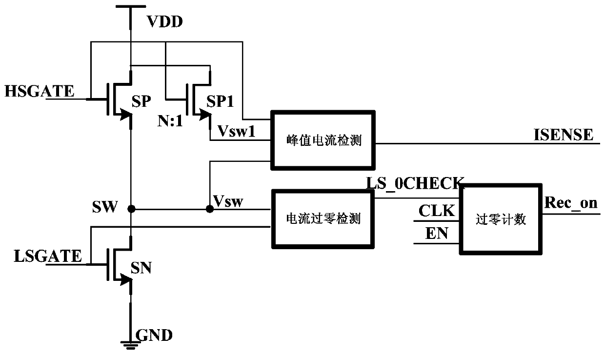
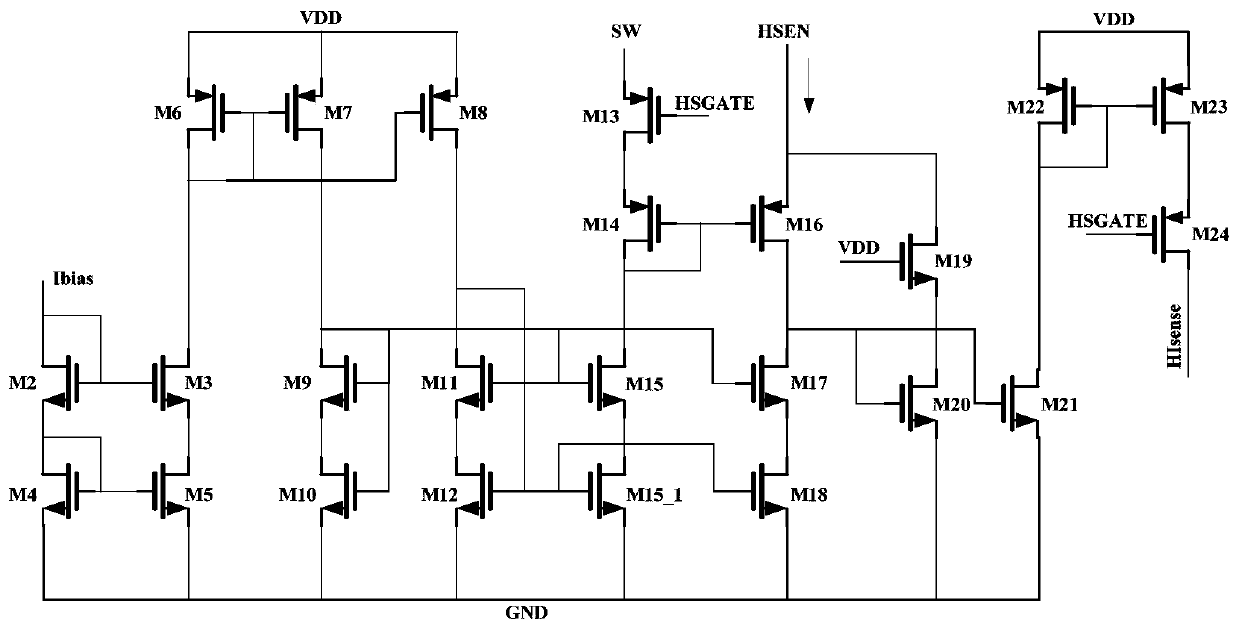
[0053] like Figure 5 As shown, it is the peak current detection simulation waveform when the size ratio of the NMOS transistor SP to the NMOS transistor SP1 is 17900:1, and the size ratio of the transistor M20 to the transistor M21 is 6:1. It can be seen from the figure that the peak current flowing through the NMOS transistor SP The peak detection current is 6A and 56mA respectively, and the ratio is about 107400:1. It has high detection accuracy and meets the accuracy requirements of circuit work.

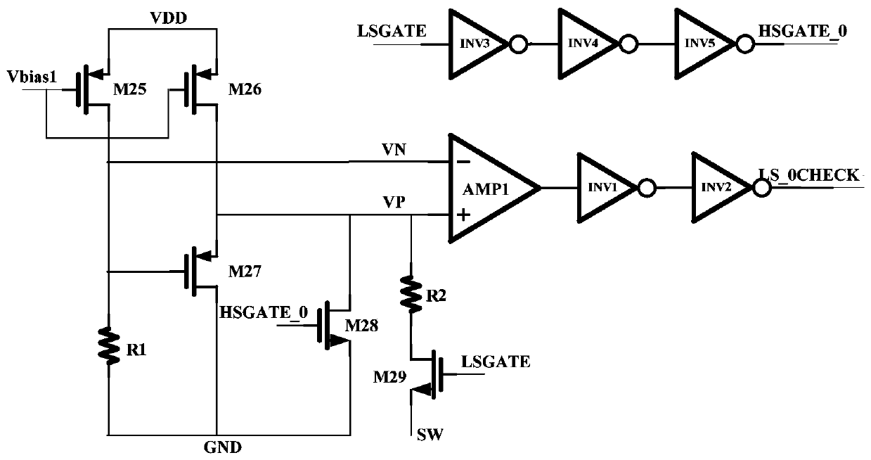
[0054] like Image 6 As shown, the current zero-crossing detection simulation waveform, in which the resistance R2 is 2.26KΩ, and the level of the VN terminal is maintained at 200mV, it can be seen from the simulation results that when the inductor current crosses zero, the LS_0CHECK terminal can accurately output a zero-crossing indication high level, with High accuracy, in line with design requirements.

[0055] like Figure 7 Shown is the simulation result of zero-crossing...


PUM


Abstract

The invention provides a current detection circuit for a PWM / PFM dual-mode DC-DC switching power supply. The detection circuit is used for carrying out high-side switching tube peak current detectionand inductive current zero-crossing detection, carrying out zero-crossing cycle counting, and when five consecutive cycles have zero crossing, triggering a PWM mode to be switched to a PFM mode. The current detection circuit is an on-chip circuit and comprises a peak current detection circuit, an inductive current zero-crossing detection circuit and a zero-crossing cycle counting circuit. By configuring source end voltage of a current mirror image tube, mirror image precision of the current is ensured; by detecting source end current of the mirror image tube, a peak current detection functionis realized; and by sampling drain end voltage of SN of an NMOS transistor, when the voltage rises from a negative level to a positive level, a zero-cross signal is output, and zero-crossing cycle counting is started, thereby realizing inductive current zero-crossing detection and counting functions. The reference circuit is simple in structure and high in precision, and is suitable for the PWM / PFM dual-mode DC-DC switching power supply.

Description

technical field [0001] The invention relates to a current detection circuit, in particular to a current detection circuit for a PWM / PFM dual-mode DC-DC switching power supply, which belongs to the technical field of analog integrated circuits. Background technique [0002] In the PWM / PFM dual-mode DC-DC switching power supply circuit, the peak current detection module is the key module of the entire current loop. This module is mainly used to detect the power tube current when the power tube is turned on in each cycle and feed it back to the internal circuit. Perform peak current limit and slope compensation, therefore, the accuracy of current detection directly affects the control accuracy of the current loop, and also controls the switching time of the switch tube to a certain extent, and further affects the accuracy of the output voltage, so the design A high-precision peak current detection circuit has an important impact on the accuracy of the DC-DC power supply. [00...

Claims


Application Information

Patent Timeline
Patent Type & Authority Patents(China)
IPC IPC(8): G01R31/327G01R19/175
Inventor 李卓孔瀛莫艳图宋奎鑫陈莉明高鹏周硕
Owner BEIJING MXTRONICS CORP
Learn More