
Self-obstruction type transmission line deicing device

A transmission line, self-obstacle-over technology, applied in cable installation, overhead installation, electrical components, etc., can solve problems such as danger, spring deformation reduction, and inability to automatically climb over, etc., to achieve low manpower investment and high efficiency Effect

Inactive Publication Date: 2019-08-06
国网河南省电力公司桐柏县供电公司
View PDF3 Cites 0 Cited by
  • Summary
  • Abstract
  • Description
  • Claims
  • Application Information

AI Technical Summary

Problems solved by technology

When the clamping obstacle-crossing device encounters the spacer, the front and rear travel wheels contact the upper part of the spacer, and the clamping wheel matched with the front and rear travel wheels contacts the lower part of the spacer. Under the further action of the driving force, the spacer forces the slider to Move downwards in the vertical chute to further compress the elastic member. When the obstacle-crossing device is clamped to complete the obstacle-crossing of the spacer bar, the distance between the front and rear traveling wheels and the corresponding clamping wheels decreases, and the shape of the spring in the vertical chute The variable is reduced accordingly, and the deformation of the initial working state is restored, but the clamping obstacle climbing device cannot automatically climb over obstacles in the vertical direction
[0006] When the above deicing device is installed, personnel need to go up to the corresponding iron tower for high-altitude installation, and high-altitude climbing in ice-covered weather is very dangerous

Method used


Image

  • Self-obstruction type transmission line deicing device
  • Self-obstruction type transmission line deicing device
  • Self-obstruction type transmission line deicing device

Examples


Embodiment 1

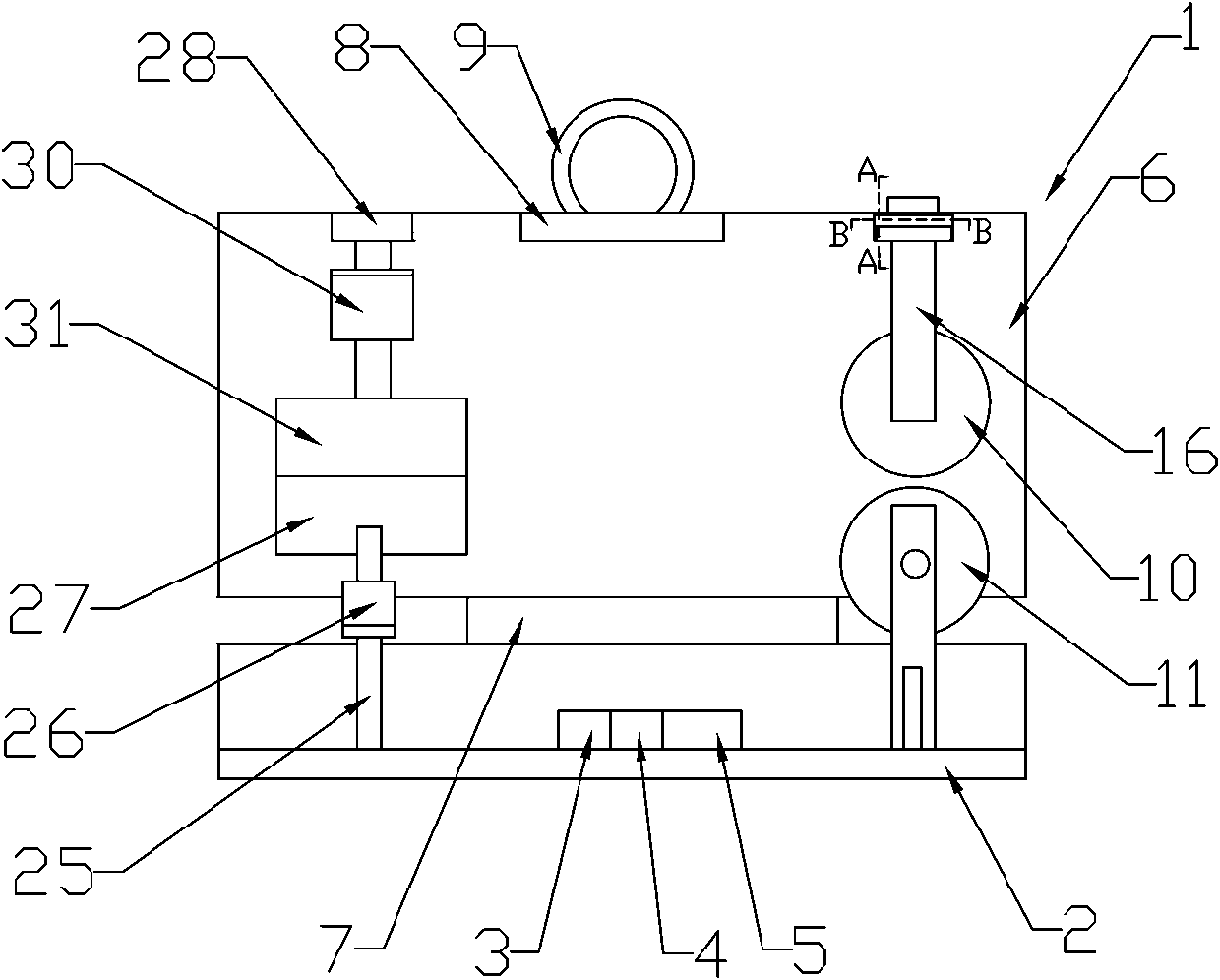
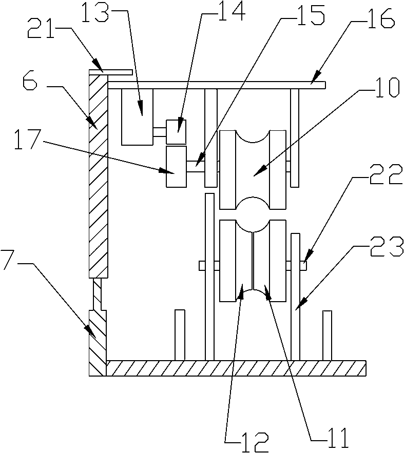
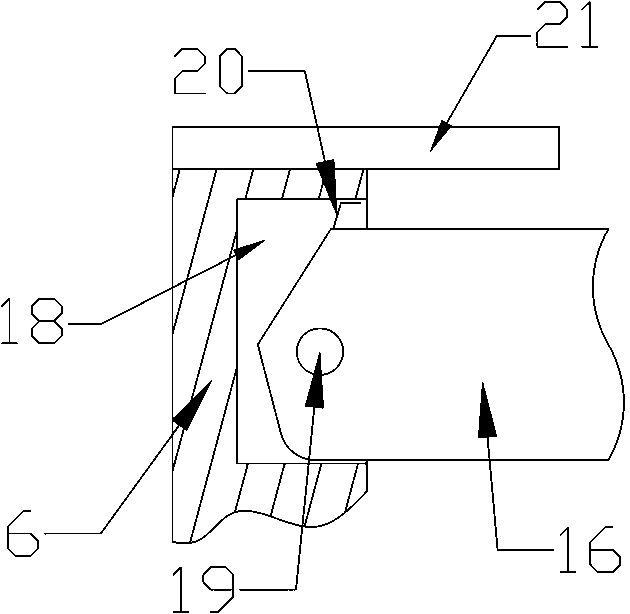
[0035] Such as figure 1 As shown, the deicing device for the self-obstacle-over power transmission line includes a frame body 1, and a deicing mechanism and a walking mechanism arranged in the frame body 1; the frame body 1 includes a bottom plate 2 and a One end is a vertical plate driven by a power mechanism to realize length adjustment, and the bottom plate 2 is provided with a power supply mechanism 3, a control mechanism 4 connected to the power supply mechanism 3, and a signal transmitting and receiving mechanism 5 connected to the control mechanism 4, The control mechanism 4 adopts a single-chip microcomputer, and the signal transmitting and receiving mechanism 5 adopts a GPRS module; the riser includes a first riser 6 and a second riser 7 set in the first riser 6, and the first riser The riser 6 and the second riser 7 are both hollow structures, and the first riser 6 is provided with a motor, a drive screw connected to the output end of the motor, a drive nut matched w...

Embodiment 2

[0042] Such as figure 1 and Figure 7 As shown, this embodiment is basically the same as Embodiment 1, the difference is that the pressing wheel I11 and the pressing wheel II12 are driven by the power mechanism to walk along the length direction of the wire, and the pressing wheel I11 and the pressing wheel II12 The power mechanism adopts the servo motor II42, and the active helical gear 40 is driven by the servo motor II42. The pressing wheel I11 and the pressing wheel II12 are arranged on the vertical support 23 through the rotating shaft II22, and one end of the rotating shaft II22 is connected with the The driven helical gear 41 matched with the driving helical gear 40, the servo motor II42 is fixed on the vertical bracket 23 and connected with the control mechanism 4.

[0043] The pressing wheel I11 and pressing wheel II12 are driven by the power mechanism to walk along the wire, and cooperate with the traveling wheel 10 to jointly promote the walking of the deicing devi...

Embodiment 3

[0045] Such as figure 1 and Figure 8 As shown, the present embodiment is basically the same as the second embodiment, the difference is that an L-shaped connecting rod 43 is arranged on the outer wall of the first riser 6, and the direction of the interphase spacer bar on the double-split conductor is determined according to the The orientation of the connecting rod 43 is that if the interphase spacer is located on the lower side of the conductor, the connecting rod 43 faces upward, otherwise, the connecting rod 43 faces downward. According to the deicing requirements of the double-split wires, a crossbar driven by a power mechanism to adjust the length is connected between the two connecting rods 43, and the crossbar includes a first crossbar 44 and a first crossbar 44 sleeved in the first crossbar 44 Two crossbars 45, the first crossbar 44 and the second crossbar 45 are hollow structures, and the first crossbar 44 is provided with a motor, a transmission screw connected to...


PUM


Abstract

The invention discloses a self-obstacle-crossing power transmission line deicing device. The self-obstacle-crossing power transmission line deicing device comprises a frame, a deicing mechanism and awalking mechanism, and the deicing mechanism and the walking mechanism are arranged in the frame; the frame comprises a base plate and a vertical plate which is arranged on one end of the base plate and has adjustable length, and a pressure plate is provided with a power supply mechanism; the walking mechanism comprises a walking wheel driven by a power mechanism, and a compaction wheel I and a compaction wheel II, and the walking wheel, the compaction wheel I and the compaction wheel II form a concentric cavity; the walking wheel is hinged to one end, of the vertical plate, being far from thepressure plate through a shaft rod by means of a horizontal support; the compaction wheel I and the compaction wheel II are hinged to the base plate through shaft rods by means of vertical supports;each shaft rod is provided with a torsion spring; the base plate is provided with a control mechanism and a signal transmitting and receiving mechanism connected with the control mechanism, and the vertical plate achieves length adjustment when being driven by the power mechanism. The self-obstacle-crossing power transmission line deicing device can automatically climb over obstacles in the horizontal and vertical directions, and the deicing device is installed and recovered through an unmanned plane.

Description

technical field [0001] The invention relates to the technical field of deicing power transmission lines, in particular to a self-obstacle-over-obstacle deicing device for power transmission lines. Background technique [0002] Icing transmission lines in winter is one of the biggest natural disasters in power systems. Rime is formed when freezing rain falls on objects with a temperature below freezing. If it is condensed on the wire, it forms wire icing. The icing of wires will cause great damage to lines, iron towers, etc., and the repair of accidents such as power supply interruptions caused by icing is difficult and takes a long time. [0003] At present, for 220KV transmission lines, double-split conductors are generally arranged. In order to prevent the double-split sub-conductors from attracting each other, colliding, and twisting together under the action of wind, a two-split spacer is installed between the two conductors. To better prevent breeze vibration and imp...

Claims


Application Information

Patent Timeline
Patent Type & Authority Patents(China)
IPC IPC(8): H02G7/16
Inventor 罗大虎李兵杨鹏
Owner 国网河南省电力公司桐柏县供电公司
Learn More