Geothermal well inside heat exchange pipe installing process

The technology of a heat exchange tube and an installation process is applied in the field of the installation process of the heat exchange tube in a geothermal well, which can solve problems such as difficulty in using geothermal energy, and achieve the effect of solving the difficulty in use.

Inactive Publication Date: 2018-01-12
青海九零六工程勘察设计院有限责任公司 +2
View PDF4 Cites 4 Cited by
  • Summary
  • Abstract
  • Description
  • Claims
  • Application Information

AI Technical Summary

Problems solved by technology

[0003] The invention proposes a heat exchange tube installation process in a geothermal well, which solves the problem of difficult use of geothermal energy at present. A stepped hole is drilled on the ground, and several layers of oil pipelines with different diameters are respectively fitted and inserted into the hole. Water flow i

Method used


Image

  • Geothermal well inside heat exchange pipe installing process
  • Geothermal well inside heat exchange pipe installing process

Examples


Embodiment 1

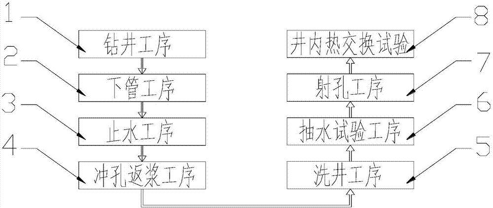
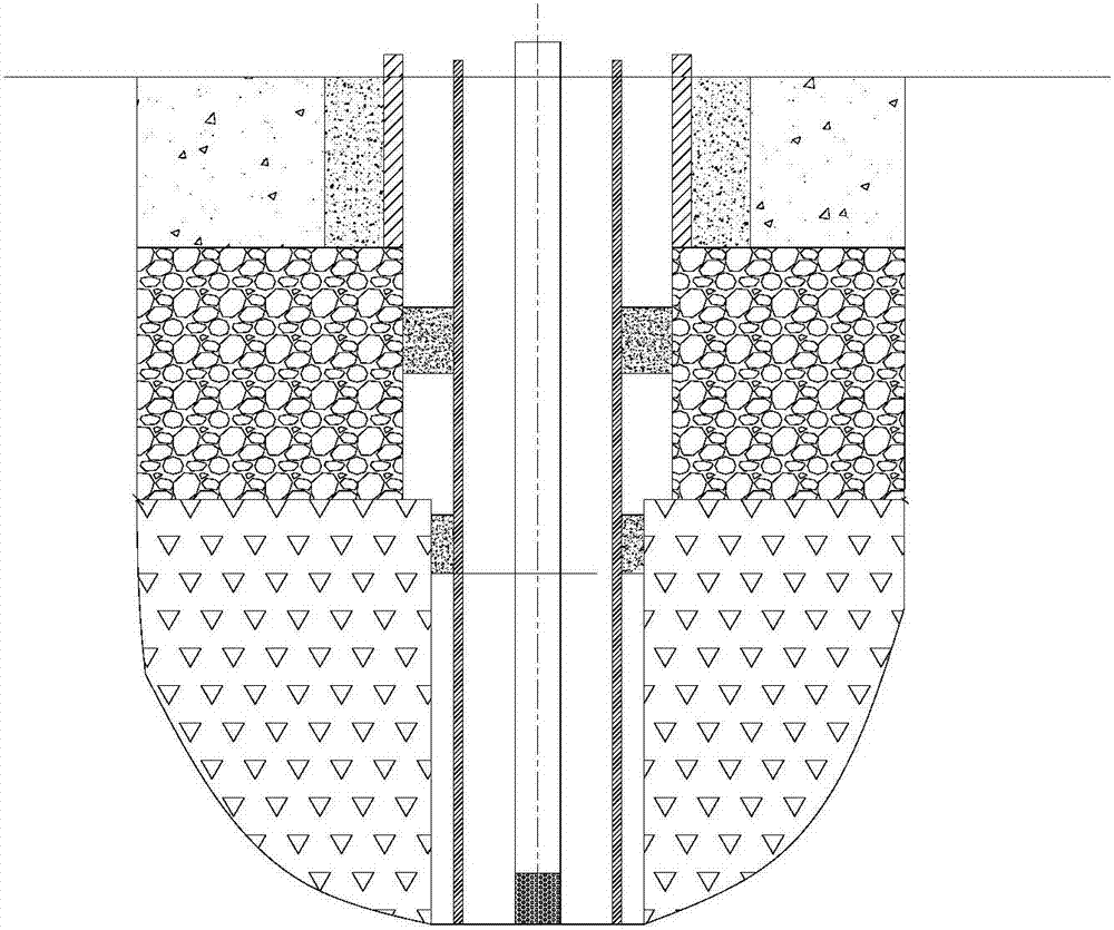
[0029] Such as Figure 1-2 As shown, the present invention provides a heat exchange tube installation process in a geothermal well, including drilling process, pipe lowering process, water stop process, punching and slurry return process, well cleaning process, pumping test process, perforation process and heat exchange experiment in the well The drilling process includes the first spud and the second spud. The first spud is to use a roller cone bit with a diameter of 445 mm to drill to 201.30 meters to form a well section of the pump chamber, and then run a pump with a diameter of 340 mm. From the chamber pipe to the bottom of the pump chamber well section, keep the pump chamber pipe 0.38 meters above the ground. After the pump chamber pipe is lowered, use the high-pressure pumping method to press in cement slurry with a specific gravity of 1.85 from the bottom of the well to the wellhead. The cement is solidified for 24 hours and the second spud is performed. The second spud...


PUM


Abstract

The invention discloses a geothermal well inside heat exchange pipe installing process. The geothermal well inside heat exchange pipe installing process includes a well drilling procedure, a pipe installing procedure, a water stopping procedure, a punching fluid returning procedure, a well washing procedure, a water drawing test procedure, a perforation procedure and a well inside heat exchange experiment procedure. A stepped hole is drilled in the ground through the well drilling procedure. A plurality of layers of petroleum pipelines with different diameters are combined in a sleeved mode and inserted into the hole through the pipe installing procedure, and water is stopped through the water stopping procedure. A well body is detected through the punching fluid returning procedure, the well washing procedure, the water drawing test procedure, the perforation procedure and the well inside heat exchange experiment procedure. Water flow is injected into the pipelines so that heat energyat the bottom end of the hole can be absorbed to heat a water body. Finally, a water drawing pipe with a water-permeable hole in the bottom end is inserted into each petroleum pipeline to draw out the hot water at the bottom end of the hole, so that heat energy in the earth crust is led out. The problem that geothermal energy resources are difficult to use at present is solved, and good practicalvalue is realized.

Description

technical field [0001] The invention relates to a heat exchange tube installation process, in particular to a heat exchange tube installation process in a geothermal well. Background technique [0002] Geothermal energy is heat energy originating within the Earth, which is produced by the decay of radioactive materials within the Earth. Geothermal energy has huge reserves, but limited by the way of use, its utilization rate is limited. At present, only a few areas use geothermal energy for power generation. The trend of geothermal energy is that the closer to the surface, the lower the geothermal temperature, and the higher the inner core temperature, so people choose to drill wells in suitable areas, and then lower the pipelines and inject water bodies to replace and carry the high-temperature water bodies inside the earth's crust. come out. However, how to implement the installation process of the operation is the key to the success. Contents of the invention [0003]...

Claims


Application Information

Patent Timeline
IPC IPC(8): E21B7/00E21B7/20E21B21/00E21B33/13E21B33/12E21B43/10F24T10/20
CPCY02E10/10
Inventor 赵振陈惠娟罗银飞蒋巍张伟谢振兴刘丽民
Owner 青海九零六工程勘察设计院有限责任公司
Why Eureka
Try Eureka