
A new type of face transmission device with two-stage deceleration function

A two-stage deceleration and transmission technology, which is applied to transmissions, gear transmissions, transmission parts, etc., can solve the problems of large transmissions and unsuitable installation and use of high-precision instruments, and achieve high transmission efficiency and light weight , small size effect

Active Publication Date: 2019-10-29
YIBIN UNIV
View PDF10 Cites 0 Cited by
  • Summary
  • Abstract
  • Description
  • Claims
  • Application Information

AI Technical Summary

Problems solved by technology

Although this method reduces the volume of the transmission device in the lateral direction, the volume of the transmission device in the axial direction of the worm is still relatively large, which is not suitable for installation and use in high-precision instruments

Method used


Image

  • A new type of face transmission device with two-stage deceleration function
  • A new type of face transmission device with two-stage deceleration function
  • A new type of face transmission device with two-stage deceleration function

Examples


Embodiment Construction

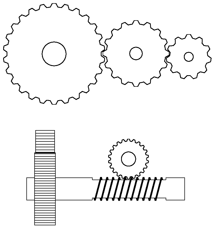
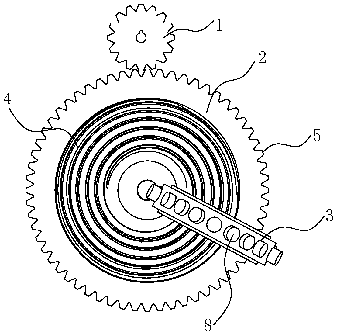
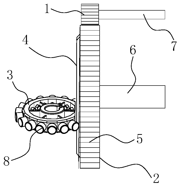
[0026] combine Figure 2-8 A new type of face transmission device with two-stage reduction function is shown, including pinion 1, transmission wheel 2 and worm wheel 3. The pinion 1 is connected with the power input shaft 7 for inputting power to the device. The worm gear 3 is connected with the power output shaft for outputting decelerated power. combine figure 2 and 3 As shown, the middle part of one end surface of the transmission wheel 2 is provided with a helical tooth 4 , the end surface of the worm wheel 3 is perpendicular to the end surface of the transmission wheel 2 , and the worm wheel 3 meshes with the helical tooth 4 . A circle of first gear teeth 5 is arranged on the peripheral surface of the transmission wheel 2 , and the first gear teeth 5 can be formed by machining, of course, can also be formed by direct die forging. The pinion 1 meshes with the first gear teeth 5, and the pinion gear 1 and the first gear teeth 5 realize the first deceleration during tra...


PUM


Abstract

The invention relates to the field of transmission devices and aims at providing a novel end face transmission device with a second-stage speed reduction function. According to the technical scheme, the novel end face transmission device with the second-stage speed reduction function comprises a small gear, a transmission wheel and a worm gear; spiral teeth are arranged in the middle of one end face of the transmission wheel, the end face of the worm gear is perpendicular to the end face of the transmission wheel, and the worm gear is engaged with the spiral teeth; a circle of first wheel teeth is arranged on the periphery of the transmission wheel, the small gear is engaged with the first wheel teeth, a support shaft is arranged on the side, away from the spiral teeth, of the transmissionwheel, and the transmission wheel is mounted on the support shaft; and the small gear is connected with a power input shaft, and the worm wheel is connected with a power output shaft. The novel end face transmission device has the beneficial effects of being small in size, compact in structure, capable of achieving large-transmission-ratio transmission and large-torque output, capable of achieving both gear transmission and worm transmission, simple in structure, low in manufacturing cost and convenient to spread and popularize.

Description

technical field [0001] The invention relates to the field of transmission devices, in particular to a novel end face transmission device with a two-stage deceleration function. Background technique [0002] At present, the two-stage reduction transmission device adopted in the prior art includes: a combination of multiple gears or a gear set plus a worm gear set. Such as figure 1 As shown, the method of combining multiple gears usually includes three gears, large, medium and small, and the three gears mesh in turn to realize two-stage reduction transmission. Although the principle structure is relatively simple, this method is usually bulky and due to two The large inter-tooth clearance of the set of meshing teeth leads to poor transmission accuracy and cannot meet the needs of high-torque transmission. The way of using the gear plus worm gear set is usually to set a large gear at one end of the worm, the large gear meshes with the small gear for power input, and the other...

Claims


Application Information

Patent Timeline
Patent Type & Authority Patents(China)
IPC IPC(8): F16H1/20F16H1/24F16H55/08F16H55/10F16H57/04
CPCF16H1/203F16H1/24F16H55/08F16H55/10F16H57/043
Inventor 陈守安
Owner YIBIN UNIV
Learn More