Method for measuring structural deformation of ballastless rail in real time based on piezoelectric ceramic technology

A technology of piezoelectric ceramics and ballastless track, which is applied in the direction of electric/magnetic solid deformation measurement, electromagnetic measurement device, and the use of stable tension/pressure test material strength, etc., which can solve the problem of aggravated maintenance costs and difficulties in meeting expectations Problems such as detection effect, large manpower and material resources are consumed, and the effect of improving detection accuracy and timeliness, reducing manual cycle detection, and ensuring safe driving

Inactive Publication Date: 2018-01-12
WUHAN UNIV OF TECH
View PDF6 Cites 7 Cited by
  • Summary
  • Abstract
  • Description
  • Claims
  • Application Information

AI Technical Summary

Problems solved by technology

In ballastless track, which has been widely used in recent years, the core is to control track deformation. The measurement of track deformation data plays an important role in track maintenance. For special road sections that are prone to deformation and damage, not only high-frequency periodic detection is required, And the detection method is limited by the environment, the accuracy rate is not high
For rails of different materials, different detection methods must be used, and the methods are difficult to unify. Each detection also consumes a lot of manpower and material resources, which increases maintenance costs and affects the normal operation of the train during the detection period.
These problems reduce the detection efficiency, make it difficult to achieve the expected detection effect, and increase the risk when the train is running

Method used


Image

  • Method for measuring structural deformation of ballastless rail in real time based on piezoelectric ceramic technology
  • Method for measuring structural deformation of ballastless rail in real time based on piezoelectric ceramic technology
  • Method for measuring structural deformation of ballastless rail in real time based on piezoelectric ceramic technology

Examples


Embodiment Construction

[0028] In order to have a clearer understanding of the technical features, purposes and effects of the present invention, the specific implementation manners of the present invention will now be described in detail with reference to the accompanying drawings.

[0029] The present invention proposes a method for real-time measurement of structural deformation of ballastless track based on piezoelectric ceramic technology, comprising the following steps:

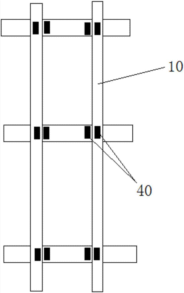
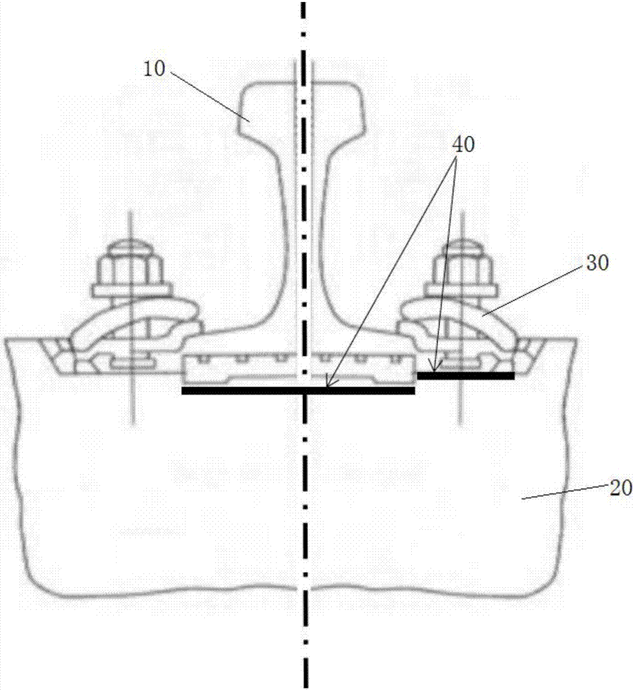
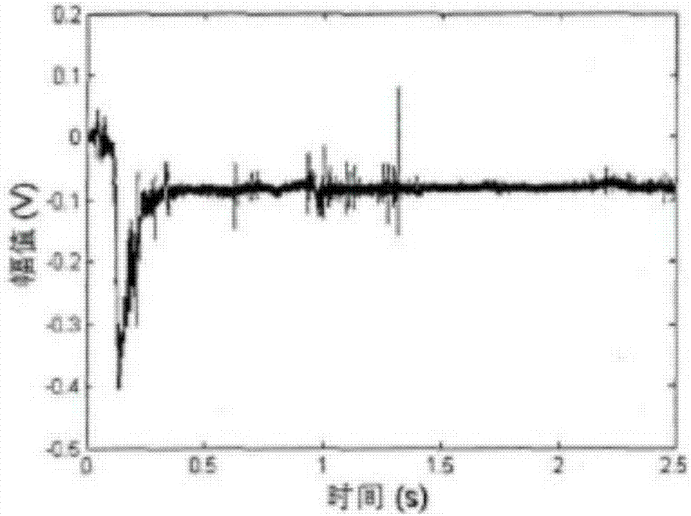
[0030] Step 1, load experiment test, install the piezoelectric ceramic sensor 40 on the ballastless track circuit simulated in the laboratory, apply loads to the rail 10 step by step until the rail 10 is deformed, cracked and destroyed, observe and record the applied load values ​​under different deformation states size F, and at the same time measure the voltage amplitude V corresponding to the output of the piezoelectric ceramic sensor 40 .

[0031] When damage and defects occur in equipment and structures, such as cracks, l...


PUM


Abstract

The invention relates to a method for measuring structural deformation of a ballastless rail in real time based on a piezoelectric ceramic technology. The method comprises the following steps: monitoring impact self-vibration deformation of a member in different directions; generating different frequencies via self-vibration of a structure when a structural stress is changed; sensing a corresponding frequency value by using a piezoelectric ceramic sensing chip attached to a surface of a steel rail; transmitting the corresponding frequency value by using the piezoelectric ceramic sensing chip as a high-frequency stress wave transmitting carrier; guiding a signal into a rail information transmission line; processing a received digital signal by using a host computer; establishing a relationship between structural deformation and structural vibration frequency; acquiring the structural vibration frequency at a rail using stage to compare with an 'f-Epsilon' deformation diagram, judging deformation or cracking situations of the rail so as to measure the structural deformation of the rail. The method provided by the invention can detect structural deformation and damage of the steel rail caused by foundation settlement in special sections for a long term, record deformation of steel momentarily, reflect whether the steel rail needs to be replaced or not, and improve detection accuracy and timeliness.

Description

technical field [0001] The invention relates to the technical field of track damage and deformation measurement, in particular to a real-time measurement method for ballastless track structure deformation based on piezoelectric ceramic technology. Background technique [0002] With the rapid development of high-speed railways, the continuous increase of railway traffic volume and long-term increase in operating time, the rails of the line have been severely fatigued. Although most of the main line has been replaced with 60kg / m seamless steel rails, various factors have caused the rails on the line to be in service for an extended period of time, which has brought great challenges to traffic safety. Therefore, it is necessary to carry out flaw detection on the rails on the line periodically. With the increase of coverage rate, the frequency of track damage and repair increases, and the detection of rail deformation and cracking becomes very significant. Especially in ballast...

Claims


Application Information

Patent Timeline
Patent Type & Authority Applications(China)
IPC IPC(8): G01N3/08G01B7/16
Inventor 方明镜王永安
Owner WUHAN UNIV OF TECH
Why Eureka
Try Eureka