
Method for evaluating coupling relationship between collision waveform and restraint system property

A technology of restraint system and coupling relationship, which is applied in the field of evaluation of the coupling effect between automobile body structure and restraint system, and can solve problems such as time-consuming and huge amount of calculation.

Active Publication Date: 2018-01-12
JILIN UNIV
View PDF4 Cites 15 Cited by
  • Summary
  • Abstract
  • Description
  • Claims
  • Application Information

AI Technical Summary

Problems solved by technology

[0004] The technical problem to be solved by the present invention is to overcome the problem of large amount of calculation and time-consuming CAE simulation technology in the study of the coupling relationship between the vehicle body structure and the occupant restraint system characteristics, and to provide an evaluation method for the coupling relationship between the collision waveform and the restraint system characteristics

Method used

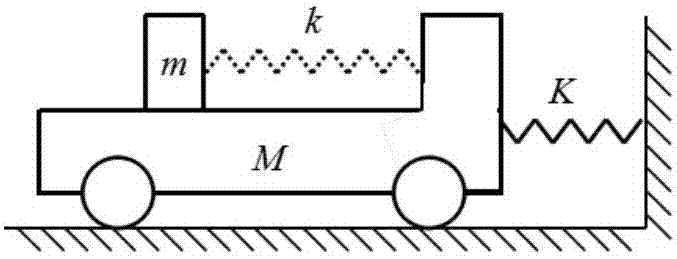
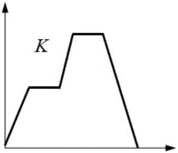

Image

  • Method for evaluating coupling relationship between collision waveform and restraint system property
  • Method for evaluating coupling relationship between collision waveform and restraint system property
  • Method for evaluating coupling relationship between collision waveform and restraint system property

Examples


Embodiment 1

[0203] Evaluation of Coupling Relationship between Collision Waveform and Restraint System Characteristics of M6 Vehicle

[0204] This embodiment evaluates the collision waveform, the restraint system characteristics and the coupling relationship between the collision waveform and the restraint system characteristics of the M6 ​​vehicle model according to the evaluation method for the coupling relationship between the crash waveform and the restraint system characteristics. The collision waveform parameters and restraint system stiffness parameters of the M6 ​​model are shown in Table 9. The evaluation method steps are as follows:

[0205] Table 9. Collision waveform and restraint system stiffness parameters of M6 vehicle

[0206]

[0207]

[0208] 1. Establishment of occupant response surface based on single-degree-of-freedom model

[0209] According to the value range and step size of the shape parameters of the equivalent double trapezoidal wave and trilinear stiffn...

Embodiment 2

[0242] In this embodiment, the simulation model of the M6 ​​occupant restraint system is used in this paper, and the three rating indicators described in the present invention are further verified in the Madymo software.

[0243] Six double-trapezoidal waveforms with α being 0, 0.2, 0.4, 0.6, 0.8, and 1 were selected from 3204 collision waveforms, as shown in Figure 8shown. In this paper, six restraint system stiffnesses corresponding to β are 0, 0.2, 0.4, 0.6, 0.8, and 1 are selected from 3136 restraint system stiffnesses, and the restraint system parameters are shown in Table 9.

[0244] Table 9 Conversion of restraint system stiffness parameters into restraint system parameters

[0245]

[0246] The selected six waveforms are sequentially used as the acceleration field of the simulation model of the M6 ​​occupant restraint system, and the restraint system remains unchanged, and the corresponding occupant chest acceleration response curve is obtained through simulation ...


PUM


Abstract

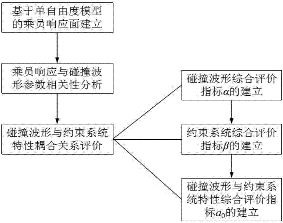
The present invention discloses a method for evaluating the coupling relationship between the collision waveform and the restraint system property, and overcomes the problem that the CAE simulation technology has huge calculation amount and is time-consuming when the coupling relation between the vehicle body structure and the occupant restraint system is studied. The method comprises: 1. establishment of the occupant response surface based on the single-degree-of-freedom model: 1) defining shape parameters of a dual trapezoidal wave and a trilinear constraint stiffness curve, 2) solving the occupant response surface with the single-degree-of-freedom model, and 3) respectively averaging the response surface in the X and Y directions; 2. correlation analysis of occupant response and collision waveform parameters: 1) carrying out supplementary definition on the collision waveform parameters, and 2) extracting the correspondence between basic parameters of the collision waveform and the Av from the occupant response surface, and carrying out linear correlation analysis; and 3. evaluation of the coupling relation between the collision waveform and the restraint system property: 1) establishing the comprehensive evaluation index alpha of the collision waveform, 2) establishing the comprehensive evaluation index beta of the restraint system, and 3) establishing ao of the comprehensive evaluation index of the collision waveform and the restraint system.

Description

technical field [0001] The present invention relates to an evaluation method for the coupling effect of an automobile body structure and a restraint system. More specifically, the present invention relates to an evaluation method for the coupling relationship between a collision waveform and a restraint system characteristic. Background technique [0002] The safety of a car is determined by both the crashworthiness of the car body structure and the occupant restraint system. At present, the safety development process of the whole vehicle is mainly to match the restraint system after the crashworthiness design of the whole vehicle structure. With the in-depth research in these two fields, enterprises have successively carried out the development of crashworthy structures and restraint system devices from various aspects. Since the crashworthiness design of the car body is in the early stage of the safety development process, it is not yet possible to establish a direct rela...

Claims


Application Information

Patent Timeline
Patent Type & Authority Applications(China)
IPC IPC(8): G06F17/50
Inventor 张君媛王丹琦靳阳李仲玉纪梦雪郭强舒畅姜哲陆炳全
Owner JILIN UNIV
Learn More