
Cable having versatile space portion

A space department, multi-functional technology, applied in the direction of insulated cables, cable installation, cable layout between relative moving parts, etc., can solve the problems of unable to maintain the correct bending radius, difficult to install, unstable movement, etc., to achieve improved Multifunctional use efficiency, prevention of wire damage, and effect of preventing wire knotting

Inactive Publication Date: 2018-01-12
THOMAS ENG
View PDF7 Cites 4 Cited by
  • Summary
  • Abstract
  • Description
  • Claims
  • Application Information

AI Technical Summary

Problems solved by technology

[0005] In existing cable protection and guide devices, the flexible material constituting the supporting member is stainless steel or leaf spring, which cannot maintain the correct bending radius when the bending state is displayed, the bending radius becomes larger, and there are problems such as touching obstacles at adjacent positions. It is difficult to install in the specified space, especially when stainless steel is used as a flexible material, it will break due to fatigue damage after long-term use, making it unusable
[0006] Moreover, stainless steel or leaf springs are used as the flexible material constituting the supporting member, and neither the stainless steel nor the leaf spring can be simply clipped and cut. When the length of the supporting member is lengthened, only a new supporting member has to be replaced, resulting in a waste of the supporting member, and, When bending, the torsional rigidity is low, causing resonance and making bending or straight motion unstable
[0007] At the same time, the existing cable only uses wires and multi-joint support parts, which has a limit problem in fully reflecting the needs of users.

Method used


Image

  • Cable having versatile space portion
  • Cable having versatile space portion
  • Cable having versatile space portion

Examples


Embodiment Construction

[0030] Hereinafter, embodiments of the cable having a multifunctional space portion according to the present invention will be described in detail with reference to the drawings.

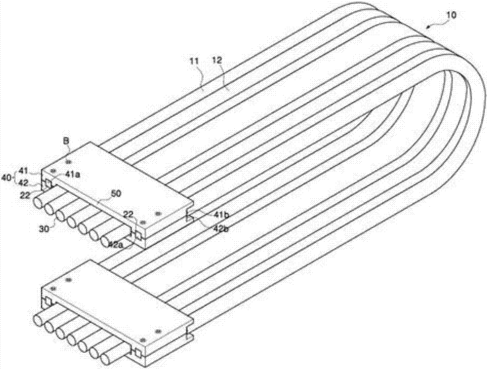
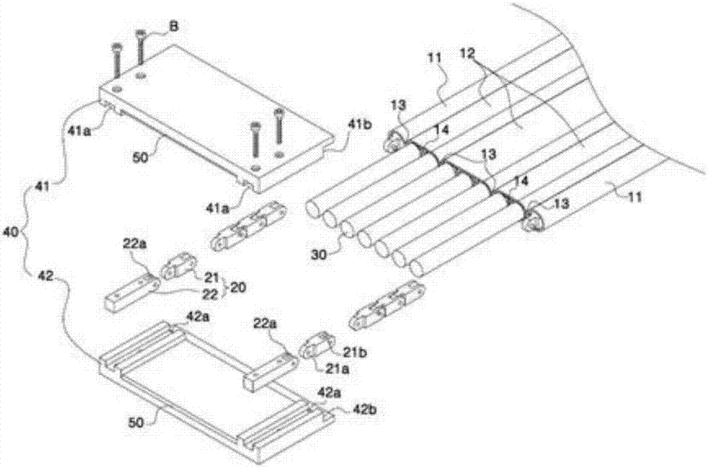
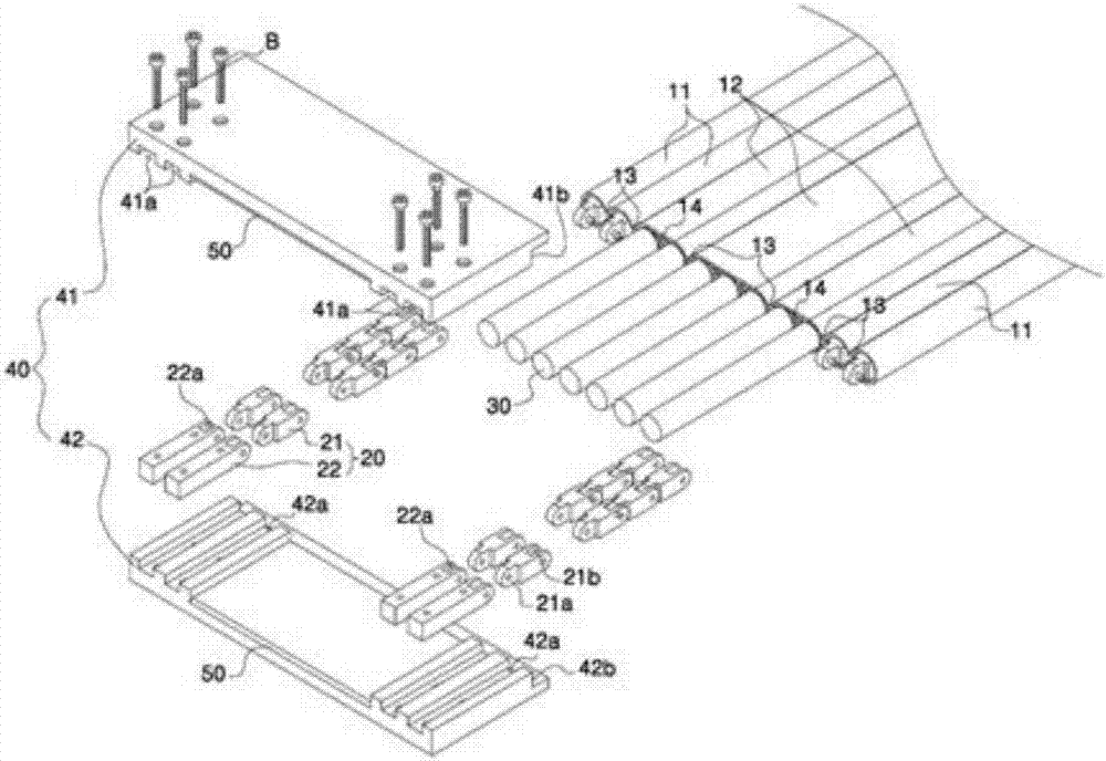
[0031] figure 1 To illustrate a perspective view of a cable with a multifunctional space part according to the first embodiment of the present invention, FIG. 2 is an exploded perspective view illustrating a cable with a multifunctional space part according to the first embodiment of the present invention.

[0032] Such as figure 1 , shown in 2, the first embodiment of the present invention has the electric wire pod (Pod, 11) that multifunctional space part cable (10) is retracted into support member inside, and the electric wire inserting part (12) that internally retracts electric wire, and inserts The support member (20) inserted into the wire pod (11), the wires (30) inserted into the wire insertion portion (12), and the pipe clamp (40) fixed to the support member (20) are constituted.

[0033...


PUM


Abstract

The present invention relates to a cable having a versatile space portion. The cable comprises: pods (11) formed on both side ends of the cable so as to contain a support member; a wire insertion portion (12) formed on a cable center portion between the pods (11) so as to contain a wire; a support member (20); multiple wires (30); and a clamp (40) comprising an upper clamp (41) and a lower clamp (42), the upper clamp (41) being installed on the upper side of the support member (20), upper insertion grooves (41a) being formed on one side of both side ends of the inner surface of the upper clamp(41) in the longitudinal direction of the clamp, upper engaging ledges (41b) being formed and positioned to face the pod on one side end or the pods on both side ends, the lower clamp (42) being installed on the lower side of the support member (20), lower insertion grooves (42a) being formed on one side of both side ends of the inner surface of the lower clamp (42) in the longitudinal directionof the clamp, and lower engaging ledges (42b) formed and positioned to face the pod on one side end or the pods on both side ends, wherein: the upper clamp (41), the support member (20), and the lowerclamp (42) are screw-coupled by a bolt (B) that successively penetrates the upper clamp (41), the support member (20), and the lower clamp (42); the wire insertion portion (12) is delimited / divided into a plurality of areas by a plurality of bonding portions (13); thermal bonding portions (14) are formed inside respective areas, into which the wire insertion portion (12) has been divided, such that a thermally bondable material, which is melted and bonded by heat, is applied therein; and, advantageously, the wires can be easily bent and maintained in straight postures, twisting and distortionof the wires can be prevented, and the force of coupling between the clamp and the support member can be enhanced.

Description

technical field [0001] The present invention relates to a cable, which can be used in working machines, electronic equipment, industrial robots, handling machines, etc., and can be used for sharp turning, liquid supply, air supply, etc. in mobile machines or moving parts of mobile machines, especially for easy maintenance of wires. A cable with a multifunctional support member insertion space that can be inserted into a support member for various purposes in curved and straight shapes according to user needs. Background technique [0002] When connecting cables to provide power to moving objects such as machine tools, civil engineering machinery, and transportation devices, or connecting hoses to provide hydraulic pressure or air pressure, the movement of the moving body causes excessive torsion or pulling force on the cables or hoses, resulting in cables or hoses. The hose is damaged or affects the appearance. [0003] In order to solve this kind of problem, a protective g...

Claims


Application Information

Patent Timeline
Patent Type & Authority Applications(China)
IPC IPC(8): H02G11/00H01B7/17
CPCH02G11/006H02G3/0487H01B7/17H02G11/00F16G13/16F16L3/015H01B7/1815
Inventor 成镐哲
Owner THOMAS ENG
Learn More