Fault monitoring system for ultralong optical cable and method
A fault monitoring and detection system technology, applied in optical instrument testing, machine/structural component testing, measuring devices, etc., can solve the problem of difficulty in obtaining the temperature and strain information of the optical cable at the fault point, and achieve improved judgment accuracy and high precision. Fault location and diagnosis, the effect of simple structure
- Summary
- Abstract
- Description
- Claims
- Application Information
AI Technical Summary
Problems solved by technology
Method used
Image

Examples
Embodiment Construction
[0037] In order to make the technical problems, technical solutions and advantages to be solved by the present invention clearer, the following will describe in detail with reference to the drawings and specific embodiments.
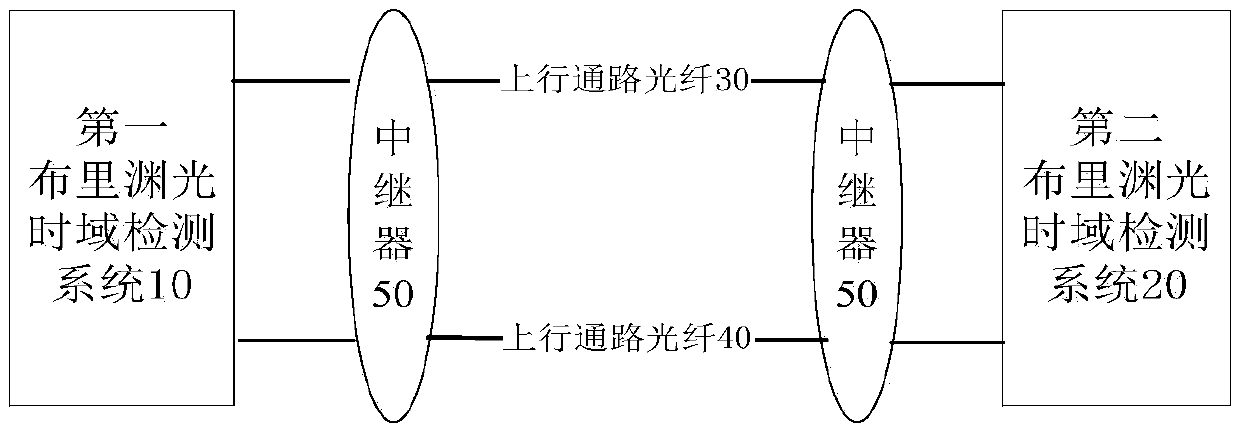
[0038] On the one hand, if figure 1 As shown, the embodiment of the present invention provides a fault monitoring system for an ultra-long optical cable, including: a first Brillouin optical time domain detection system 10, a second Brillouin optical time domain detection system 20, an uplink optical fiber 30, The downlink optical fiber 40 and a plurality of optical repeaters 50 arranged in each section of the uplink optical fiber and the downlink optical fiber, the two ends of the uplink optical fiber and the downlink optical fiber are connected to the first Brillouin optical time domain detection system and the first Brillouin optical time domain detection system respectively. The second Brillouin optical time domain detection system is connected, the ...
PUM
 Abstract
Description
Claims
Application Information
 - Generate Ideas
- Intellectual Property
- Life Sciences
- Materials
- Tech Scout
- Unparalleled Data Quality
- Higher Quality Content
- 60% Fewer Hallucinations
Browse by: Latest US Patents, China's latest patents, Technical Efficacy Thesaurus, Application Domain, Technology Topic, Popular Technical Reports.
© 2025 PatSnap. All rights reserved.Legal|Privacy policy|Modern Slavery Act Transparency Statement|Sitemap|About US| Contact US: help@patsnap.com