Acquiring method of light response lines in emission imaging device

An imaging device and acquisition method technology, applied in the field of medical imaging, can solve the problems of large errors and low acquisition accuracy of optical response lines, and achieve the effects of high positioning accuracy, increased positioning error, and precise positioning

Inactive Publication Date: 2018-01-19
HUAZHONG UNIV OF SCI & TECH
View PDF8 Cites 5 Cited by
  • Summary
  • Abstract
  • Description
  • Claims
  • Application Information

AI Technical Summary

Problems solved by technology

[0003] Aiming at the above defects or improvement needs of the prior art, the present invention provides a method for obtaining the optical response line in the emission imaging device, by obtaining the energy distribution information of a pair of photons on the emission imaging device, and calculating the optical response line based on the energy distribution information Response line, thus solving the technical problems of low accuracy and large error of optical response line acquisition

Method used


Image

  • Acquiring method of light response lines in emission imaging device
  • Acquiring method of light response lines in emission imaging device
  • Acquiring method of light response lines in emission imaging device

Examples


Embodiment Construction

[0024] In order to make the objectives, technical solutions and advantages of the present invention clearer, the present invention will be further described in detail below with reference to the accompanying drawings and embodiments. It should be understood that the specific embodiments described herein are only used to explain the present invention, but not to limit the present invention. In addition, the technical features involved in the various embodiments of the present invention described below can be combined with each other as long as they do not conflict with each other.

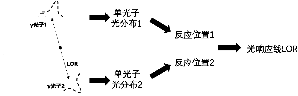
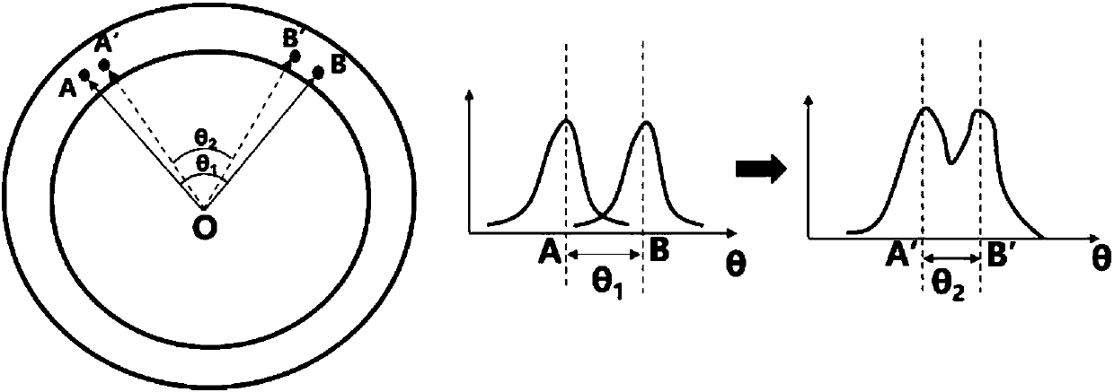
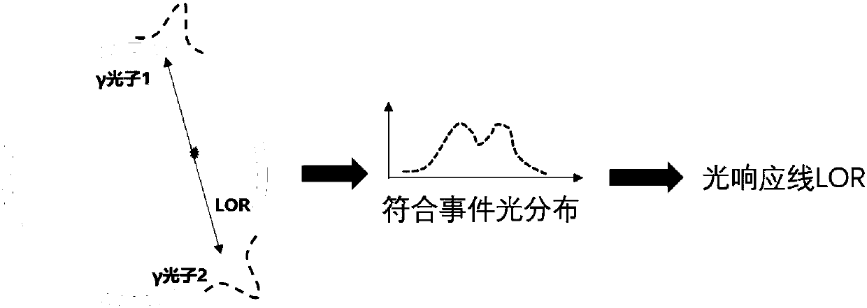
[0025] image 3 is a schematic diagram of the method for obtaining the light response line provided by the present invention constructed according to the preferred embodiment of the present invention, such as image 3 As shown in the figure, a method for obtaining light response lines in an emission imaging device, the present invention obtains a pair of photon energy distribution information at a ...


PUM


Abstract

The invention belongs to the field of medical imaging and discloses an acquiring method of light response lines in an emission imaging device. The acquiring method comprises the following steps that 1, energy distribution information of a pair of gamma photons is acquired through a positron emission imaging device, wherein the energy distribution information is acquired in pairs, different pairs of gamma photons are differentiated through a time window, a connection line of a pair of photons is a light response line to be solved, and the connection lines of multiple pairs of gamma photons aresubjected to image reconstruction so that a striograph can be obtained; 2, the light response lines are calculated by using the energy distribution information through a centroid method or an intelligent algorithm. The acquiring method of the light response lines in the emission imaging device improves the acquiring precision of the light response lines, an emission source of gamma rays is positioned, and the acquiring method is simple and high in speed.

Description

technical field [0001] The invention belongs to the field of medical imaging, and more particularly, relates to a method for acquiring light response lines in an emission imaging device. Background technique [0002] Medical Positron Emission Tomography (PET) is a representative product of international advanced medical devices. It is widely used in the early diagnosis, treatment plan formulation and prognosis prediction of tumors, cardiovascular and cerebrovascular diseases and neurodegenerative diseases. and drug efficacy ratings. The traditional emission imaging system consists of multiple independent square-shaped ray detector modules assembled and spliced ​​into a ring structure through mechanical structure, and the detectors are composed of scintillation crystal coupled photoelectric sensors (PMT, SiPM, etc.). By calculating the reaction position of γ photons on a single detector, the light response line information corresponding to the γ event is obtained, and the to...

Claims


Application Information

Patent Timeline
Patent Type & Authority Applications(China)
IPC IPC(8): A61B6/03G01T1/202
Inventor 许剑锋谢思维谢杨泽杨静梧杨明明彭旗宇
Owner HUAZHONG UNIV OF SCI & TECH
Why Eureka
Try Eureka