
Spin exchange coupling based uniform distribution device for flue gas, equipment equipped with device and working method

A cyclone and flue gas technology, applied in separation methods, chemical instruments and methods, dispersed particle separation, etc., can solve the problems of large deviation of catalyst flue gas flow rate, catalyst blockage, low denitration efficiency, etc., and reduce ammonia escape and reduction. agent consumption, ease of processing and installation, and the effect of improving denitration efficiency

Pending Publication Date: 2018-01-19
HUADIAN ELECTRIC POWER SCI INST CO LTD
View PDF6 Cites 2 Cited by
  • Summary
  • Abstract
  • Description
  • Claims
  • Application Information

AI Technical Summary

Problems solved by technology

However, due to the complex and changeable flue gas flow field at the reactor inlet of the SCR denitrification device, the NO X The concentration distribution is uneven, and the relative deviation of the local ammonia nitrogen molar ratio of the flue gas entering the reactor is relatively large, resulting in low denitrification efficiency
Especially in the context of ultra-low emission transformation, denitrification export NO X Concentration control 50mg / m 3 Even lower, reducing agent consumption and ammonia slip consumption cannot be effectively guaranteed
At the same time, due to the limited effect of the reactor inlet deflector, the flue gas flow rate into the uppermost catalyst has a large deviation, and the local flue gas flow rate is too large, causing the wear of the catalyst, and the area where the flue gas flow rate is too low will appear. deposition, which seriously causes catalyst clogging, which further aggravates catalyst deactivation
[0003] Due to its structural characteristics, the existing SCR denitrification system air distribution device has disadvantages such as long mixing time and poor mixing effect

Method used


Image

  • Spin exchange coupling based uniform distribution device for flue gas, equipment equipped with device and working method
  • Spin exchange coupling based uniform distribution device for flue gas, equipment equipped with device and working method
  • Spin exchange coupling based uniform distribution device for flue gas, equipment equipped with device and working method

Examples


Embodiment Construction

[0022] The present invention will be further described in detail below in conjunction with the accompanying drawings and examples. The following examples are explanations of the present invention and the present invention is not limited to the following examples.

[0023] Example.

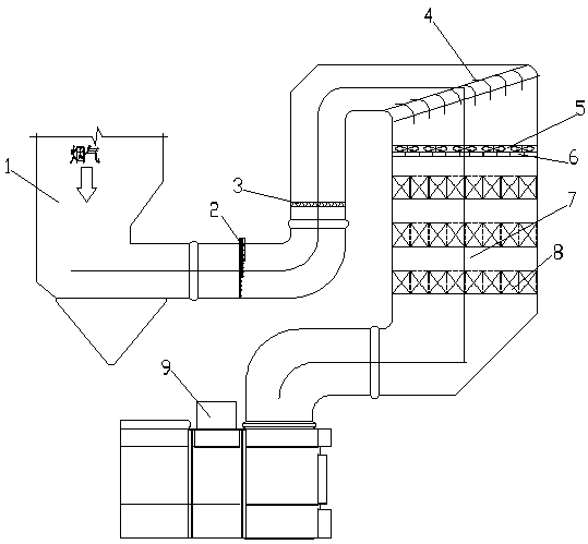
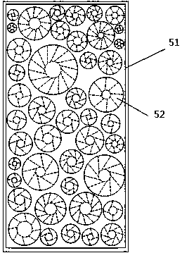
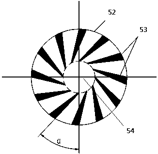
[0024] see Figure 1-4 .

[0025] This embodiment is a smoke swirl sink coupling uniform distribution device 5 , which includes a flat plate 51 and a plurality of circular flow holes 52 , and all the circular flow holes 52 are arranged on the flat plate 51 .

[0026] Each circular flow hole 52 is provided with a guide vane group, and the guide vane group includes a plurality of guide vanes 53, and the guide vanes 53 on the same circular flow hole 52 move clockwise or counterclockwise. Swirl arrangement. In this embodiment, the flat plate 51 has a circular flow hole 52 equipped with a clockwise swirling guide vane 53 and a circular flow hole 52 equipped with a counterclockwise swirling guide vane...


PUM


Abstract

The invention relates to a spin exchange coupling based uniform distribution device for flue gas, equipment equipped with the device and a working method. The device comprises a flat plate and a plurality of circular through-flow holes, wherein all the circular through-flow holes are formed in the flat plate, a guide vane group is arranged at each circular through-flow hole and comprises a plurality of guide vanes, the guide vanes at the same circular through-flow hole are arranged in a clockwise or counterclockwise swirling mode, and an imaginary circle is arranged at the center of each circular through-flow hole and is in a hole shape; one end of each guide vane is arranged at the edge of the circular through-flow hole where the guide vane is located, and the other end is arranged at theedge of each imaginary circle of the circular through-flow hole where the guide vane is located. By means of the spin exchange coupling based coupling uniform distribution device, flue gas entering an SCR (selective catalytic reduction) denitration reactor is redistributed, uniformity of the flue gas in the SCR denitration reactor can be obviously improved, erosive wear of a catalyst by high fluegas flow rate and the ash deposition condition of the catalyst in a low flue gas flow rate area are effectively improved, and the service life of the catalyst is prolonged.

Description

technical field [0001] The invention relates to a flue gas swirl sink coupling uniform distribution device, equipment and working method for installing the device. Background technique [0002] At present, the SCR flue gas denitrification process is adopted by most coal-fired generating units in my country because of its simple structure, high denitrification efficiency, and the by-products produced during the denitrification process will not cause secondary pollution. However, due to the complex and changeable flue gas flow field at the reactor inlet of the SCR denitrification device, the NO X The concentration distribution is uneven, and the relative deviation of the local ammonia nitrogen molar ratio of the flue gas entering the reactor is relatively large, resulting in low denitrification efficiency. Especially in the context of ultra-low emission transformation, denitrification export NO X Concentration control 50mg / m 3 Even lower, reducing agent consumption and ammo...

Claims


Application Information

Patent Timeline
Patent Type & Authority Applications(China)
IPC IPC(8): B01D53/90B01D53/56
Inventor 李超曲立涛于洪海焦健齐晓辉王德鑫胡冰
Owner HUADIAN ELECTRIC POWER SCI INST CO LTD
Learn More