Optical mixer without polarization state diversity

A technology of optical mixer and polarization beam splitting, applied in the field of optical mixer

Active Publication Date: 2016-10-12
SOUTHEAST UNIV
View PDF6 Cites 6 Cited by
  • Summary
  • Abstract
  • Description
  • Claims
  • Application Information

AI Technical Summary

Problems solved by technology

[0005] If it is necessary to use existing mixers in the field to mix TE mode and ...

Method used


Image

  • Optical mixer without polarization state diversity
  • Optical mixer without polarization state diversity
  • Optical mixer without polarization state diversity

Examples


Embodiment 1

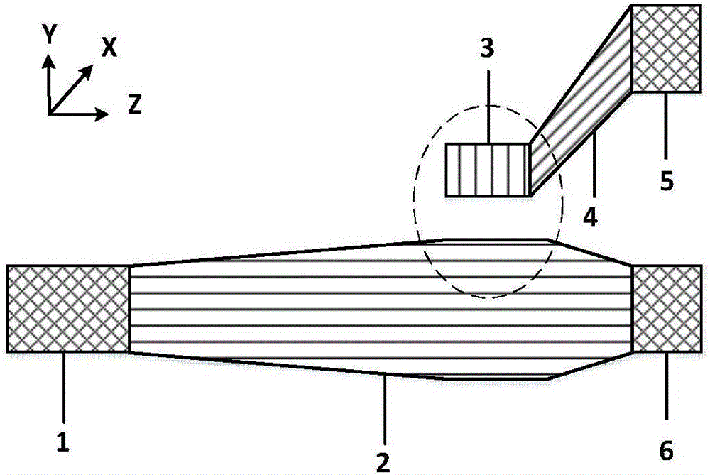
[0041] against figure 2 When the polarization-insensitive mixer implements mode conversion, according to Figure 4 It can be seen that the waveguide width does not produce mode conversion for the incident light of TE0 mode. When the incident light is in the TM0 mode, when the core width of the waveguide is appropriate, some specific polarization modes (such as the TM0 and TE1 modes in the figure) will be due to mode matching (that is, the equivalent refractive index of the mode is the same), making it Make a mode switch. We take advantage of this feature to adjust the width of the graded core waveguide to about 0.8um. At this time, the effective refractive index of the TM0 mode at the input end overlaps with the effective refractive index of the TE1 mode, thereby converting the TM0 mode into the TE1 mode. Then extract the signal of TE1 mode through coupling, and further adjust it to the synchronous output of TE0 mode.

[0042] The overall structure of this embodiment refe...

Embodiment 2

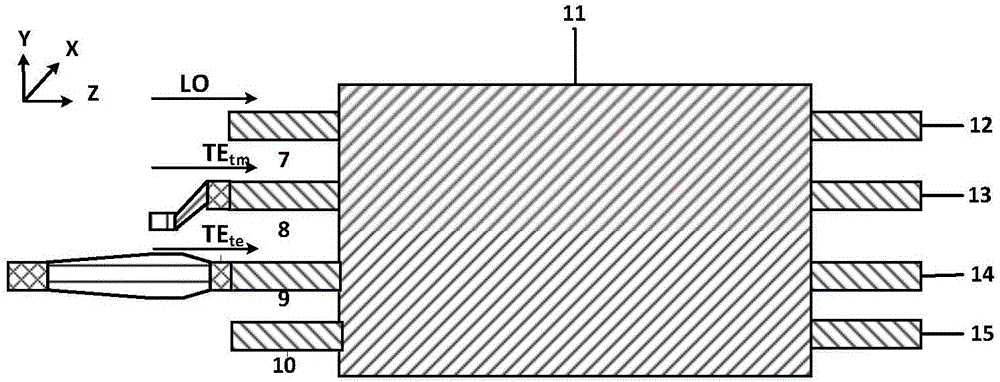
[0049] This embodiment proposes a specific mixer structure. The cascaded polarization splitter rotator (PSR) is the same waveguide structure used in the multimode interference coupler (MMI). Among them, there are four connection methods between PSR and MMI, such as Figure 9 , 10 , 11 and 12, the input waveguides connected to the second output port 5 and the first output port 6 are the second input end 8 and the first input end 9 respectively. The local signal light is input from waveguide 7 or 10; For the realization of frequency mixing with a single MMI, these 4 port combinations can realize mixing, and the ways that can be realized are listed one by one here. In the claims, the two input terminals in the middle of the multimode interference coupler refer to the input terminals connected to the waveguides 8 and 9, and the two input terminals outside the multimode interference coupler refer to the input terminals connected to the waveguides 7 and 10.

[0050] The nanoscal...


PUM

PropertyMeasurementUnit
Lengthaaaaaaaaaa
Widthaaaaaaaaaa

Abstract

The invention discloses a 90-degree optical mixer without a polarization state diversity. The 90-degree optical mixer is formed by a polarization beam splitter rotator and a multimode interference coupler (MMI) in a cascade connection. The polarization beam splitter rotator is formed by upper and low mode conversion modules in mutual coupling, inputted transverse electric mode (TE) and transverse magnetic mode (TM) are converted into transverse electric modes (TE), thus a mixer parameter can be accurately optimized regardless of an input mode, the multimode imaging positions in the MMI are maintained to be consistent in an integrated condition, and the optical mixing without polarization diversity is realized. Compared with a traditional mixer, the influence on the MMI by different mode imaging positions is made up, the inaccuracy brought by the compromise processing on the parameter in the integrated condition is avoided, and the loss and error of mixing are reduced. The optical mixer with the above structure has the characteristics of compact structure and good performance and is suitable for a coherent optical receiving system.

Description

technical field [0001] The invention relates to the optical mixer technology, in particular to a device capable of indiscriminately mixing different polarized lights. Background technique [0002] The development of coherent optical communication system has greatly improved the transmission rate, transmission capacity and transmission distance of optical communication system. The key to its successful development lies in the application of coherent receiving technology. Coherent reception technology uses homodyne or heterodyne reception to process optical signals, and the 90° optical mixer is an essential core component of these two methods. In the optical mixer, the incident light and the output light of the local oscillator source are optically mixed under the conditions of wavefront matching and polarization matching, so as to obtain a difference frequency signal carrying information such as amplitude and phase. The difference frequency signal is extracted through differ...

Claims


Application Information

Patent Timeline
IPC IPC(8): G02B6/27G02B6/28G02B6/293
CPCG02B6/2773G02B6/2813G02B6/29344
Inventor 王瑾翟羽萌孙小菡
Owner SOUTHEAST UNIV
Why Eureka
Try Eureka