Parallel double-rotor pneumatic conveying feeder

A pneumatic conveying and double-rotor technology, which is applied in the direction of conveyors, conveying bulk materials, transportation and packaging, etc., can solve the problems of inflexible air regulation, insufficient equipment feeding capacity, and low utilization of equipment space. And the configuration mode is flexible, the effect of improving equipment operation efficiency and improving filling rate

Active Publication Date: 2018-01-19
CISDI ENG CO LTD +2
View PDF12 Cites 3 Cited by
  • Summary
  • Abstract
  • Description
  • Claims
  • Application Information

AI Technical Summary

Problems solved by technology

The published Chinese patents for vertical feeders that are often used in engineering are: 201220205422.9, 201020619756.1, 201220673793.X, 201320480948.2, 201620306364.7, 201620622572.8. According to public information, a single feeder is usually a rotor and a set The transmission device has a material inlet and a material outlet, and its main disadvantages are: the utilization rate of the equipment space is low, and the feeding capacity of the equipment is insufficient; if the equipment fails, there is no thermal backup measure, and it must be shut down immediately for maintenance; usually The single-outlet feeder can only spray one reactor, so one reactor needs to be equipped with at least one feeder, and it is often necessary to configure multiple feeders for one reactor to achieve the blowing capacity; in addition At present, the air intake method of the equipment mainly adopts the side air intake method, the air intake resistance is relatively large, and the air use adjustment method is not flexible enough, resulting in a large waste of air source
[0004] The published patent 201210217828.3 is a double-channel star feeder, mainly in the form of horizontal installation, which is quite different from the traditional vertical rotary feeder in the feeding and discharging form and working mode. It is mainly in the form of a horizontal star valve , public information shows that due to its inherent characteristics, the main performance is that the filling rate of this kind of feeding and discharging structure is not high for powder materials, resulting in that this kind of form is rarely used in occasions with high precision requirements.

Method used


Image

  • Parallel double-rotor pneumatic conveying feeder
  • Parallel double-rotor pneumatic conveying feeder
  • Parallel double-rotor pneumatic conveying feeder

Examples


Embodiment Construction

[0031] The preferred embodiments of the present invention will be described in detail below with reference to the accompanying drawings.

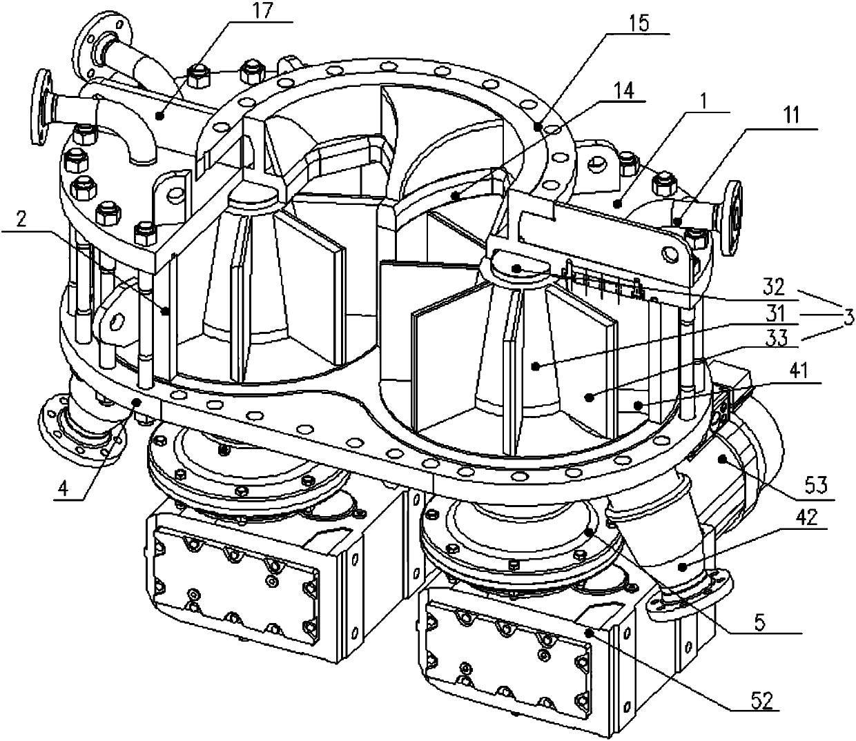
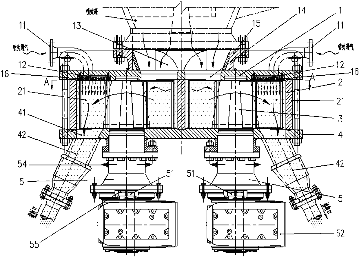
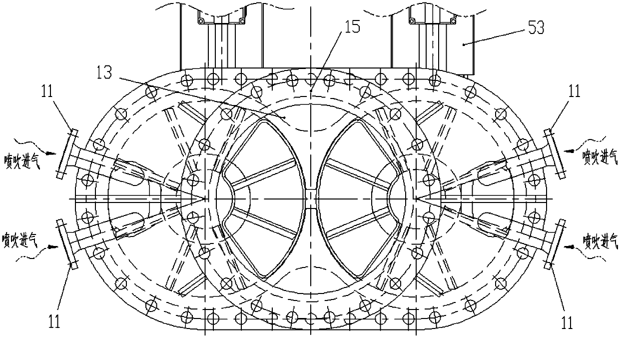
[0032] Such as Figure 1~4 , a parallel double-rotor pneumatic conveying feeder, including a top cover 1, an intermediate casing 2, a bottom plate 4, and a sealed bearing seat 5 arranged sequentially from top to bottom; the middle casing 2 and the top cover 1 and bottom plate 4 A closed impeller chamber 21 is formed, the impeller chamber 21 is provided with an impeller 3, the rotating hub 32 of the impeller 3 is connected with the upper part of the rotating shaft 51 in the sealed bearing seat 5, and the lower part of the rotating shaft 51 is connected with the The drive control system is connected, and it is characterized in that: the impeller chamber 21 and the impeller 3 have two independent side-by-side arrangements; the middle part of the top cover 1 is provided with a feed port 14 communicating with the two impeller chambers respective...


PUM


Abstract

The invention discloses a parallel double-rotor pneumatic conveying feeder applied to the field of bulk material conveying equipment. The parallel double-rotor pneumatic conveying feeder comprises a top cover, a middle shell, a baseplate and a seal bearing base; the middle shell, the top cover and the baseplate form impeller cavities; impellers are in the impeller cavities; rotating hubs of the impellers are connected with a rotating shaft in the seal bearing base; the rotating shaft is connected with a driving control system; two impeller cavities and two impellers are provided, and are arranged side by side; and two feed ports and discharge ports are correspondingly formed. The driving control system comprises a speed reducer, a variable frequency motor, a speed detecting element and aninduction plate. The parallel double-rotor pneumatic conveying feeder mainly solves the problems of low conveying precision, high intake resistance, inflexible adjusting mode, low equipment space utilization rate and low feeding capacity in traditional pneumatic conveying feeder equipment. The parallel double-rotor pneumatic conveying feeder has such advantages as high conveying precision, efficient, stable and reliable process and flexible and convenient control, and achieves excellent application prospect and value.

Description

technical field [0001] The invention belongs to the field of bulk material conveying equipment, and in particular relates to a parallel double-rotor pneumatic conveying feeder. Background technique [0002] In metallurgy and other industries, the pneumatic conveying of bulk materials has high requirements on conveying capacity and conveying precision. Using vertical rotary feeder for conveying can achieve higher conveying precision than ordinary fluidized pressurized method. The published Chinese patents of vertical feeders that are often used in engineering are: 201220205422.9, 201020619756.1, 201220673793.X, 201320480948.2, 201620306364.7, 201620622572.8. According to public information, a single feeder is usually a rotor and a set The transmission device has a material inlet and a material outlet, and its main disadvantages are: the utilization rate of the equipment space is low, and the feeding capacity of the equipment is insufficient; if the equipment fails, there is n...

Claims


Application Information

Patent Timeline
Patent Type & Authority Applications(China)
IPC IPC(8): B65G53/46B65G53/66
CPCY02P70/10
Inventor 马云峰何海熙王蜀生颜新
Owner CISDI ENG CO LTD
Why Eureka
Try Eureka