High-occlusion-limit low-temperature pump

A technology of occlusion limit and cryopump, which is applied in the direction of pumps, pump components, variable displacement pump components, etc., can solve the problems affecting the adsorption limit of cryopump, gas adsorption, poor condensation effect, etc., and achieve optimal adsorption/condensation limit, Optimized adsorption/condensation efficiency, the effect of structural form optimization

Pending Publication Date: 2018-01-19
VACREE TECH
View PDF10 Cites 7 Cited by
  • Summary
  • Abstract
  • Description
  • Claims
  • Application Information

AI Technical Summary

Problems solved by technology

Under the condition that the opening area of ​​the gas inlet is relatively limited, for the cryopump deep in the inner cavity of the cryopump, because it is far away from the suction port, the gas adsorption and condensation effects are poor, which in turn affects the adsorption limit of the entire cryopump.

Method used


Image

  • High-occlusion-limit low-temperature pump
  • High-occlusion-limit low-temperature pump
  • High-occlusion-limit low-temperature pump

Examples


Embodiment 1

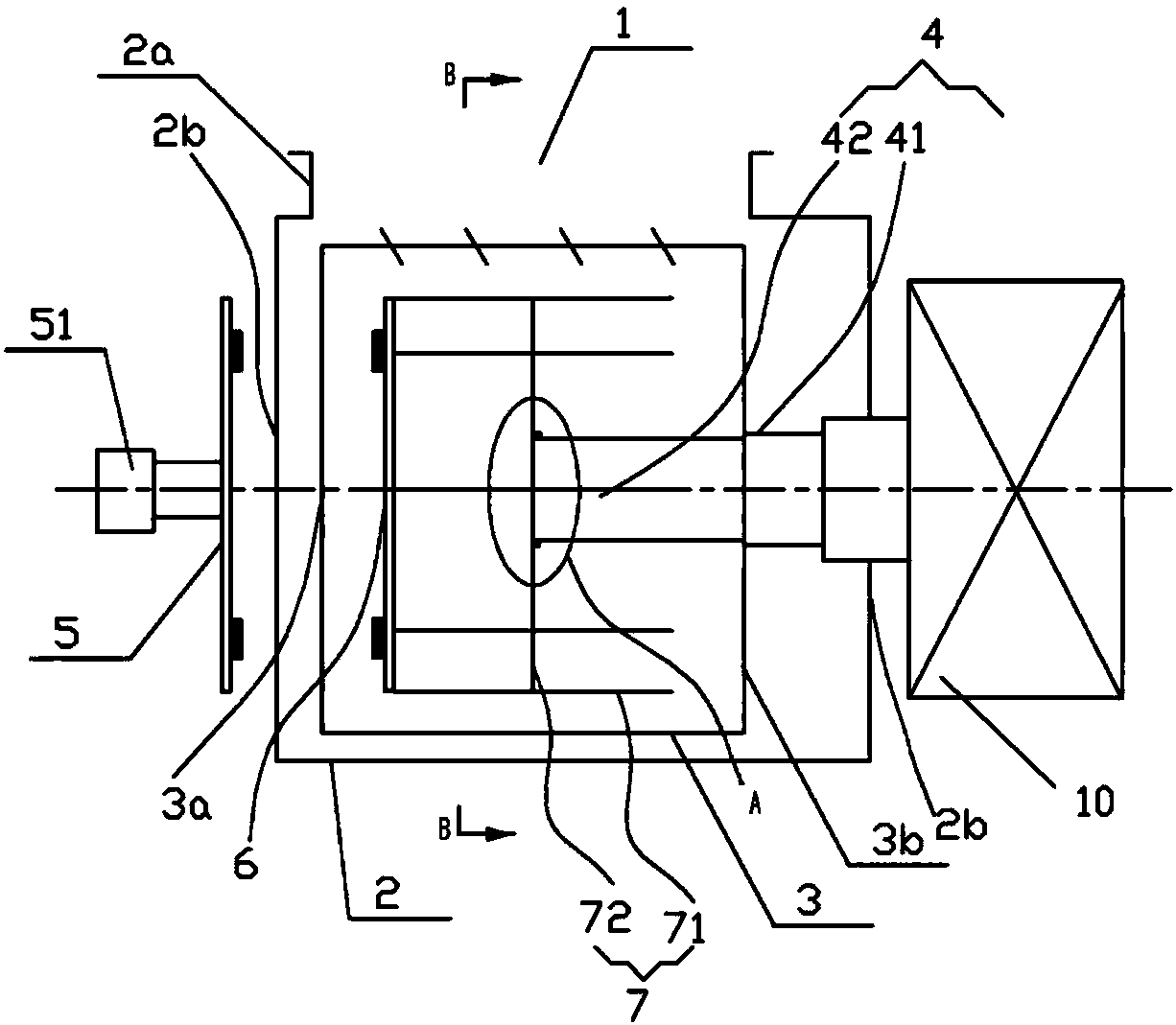
[0022] Such as Figure 1 to Figure 4 As shown, the cryopump is installed in the vacuum chamber for raising the vacuum degree in the vacuum chamber to a desired level. The cryopump has a suction port 1 for receiving gas from the vacuum chamber. The cryopump includes a casing 2, a radiation cold shield 3, a low-temperature cold source, and a cryopanel assembly 7.

[0023] The housing 2 of the cryopump is roughly cylindrical with cover plates 2b and 2c at both ends, and its axis is the central axis of the cryopump. An opening 2a (that is, the suction port of the cryopump) connected to the vacuum chamber is provided on the cylindrical surface of the housing. The opening is cylindrical and extends outward along the radial direction of the cryopump, and a flange structure is provided at the top end of the opening. The opening is preferably in the shape of a square tube.

[0024] The low-temperature cold source is a two-stage GM refrigerator. Comprising a helium compressor 10 an...

Embodiment 2

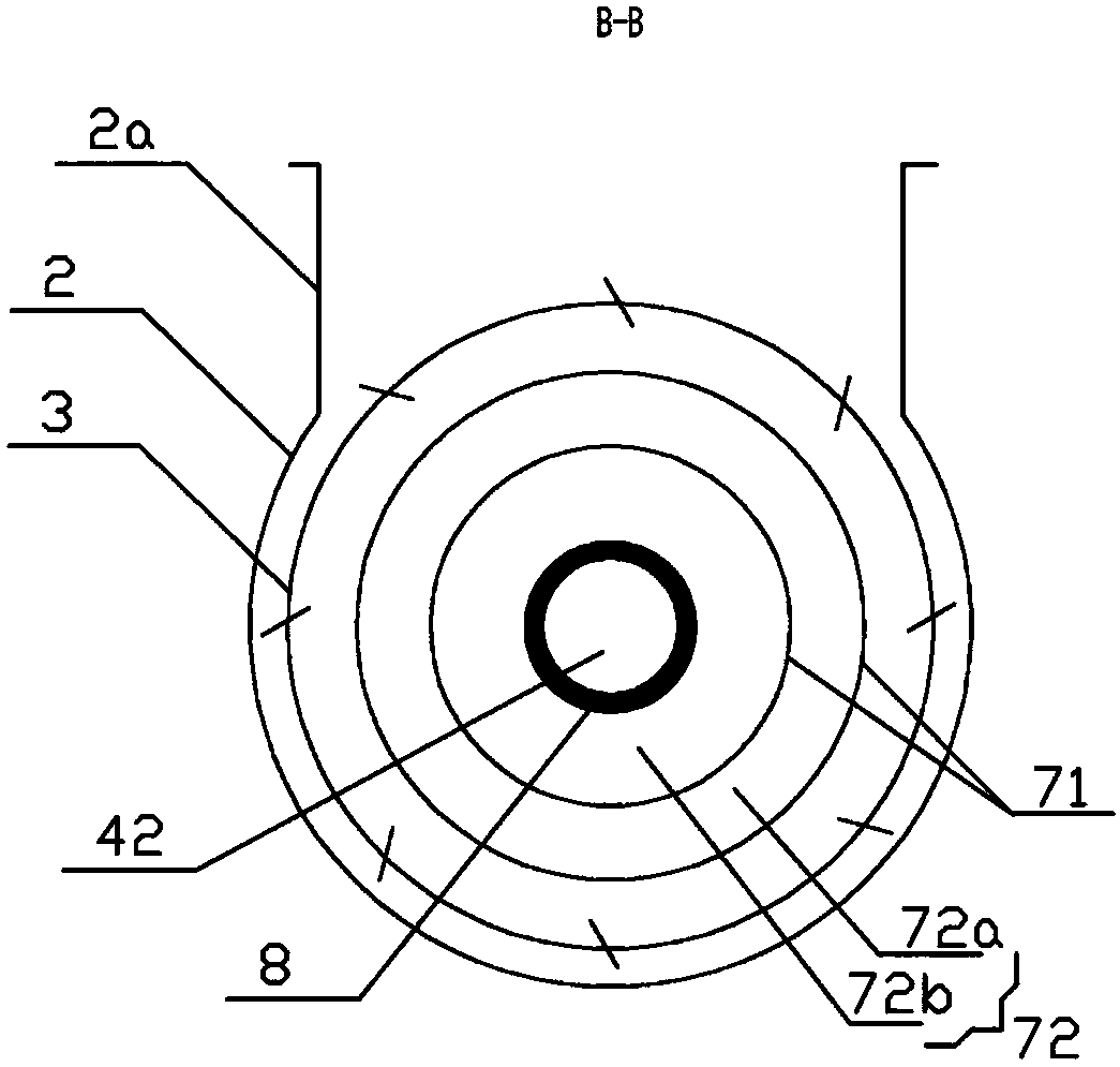
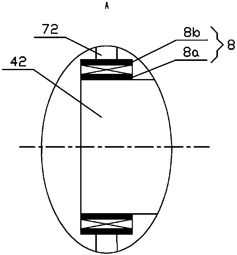
[0032] The structural composition and connection relationship of the second embodiment are roughly the same as those of the first embodiment. The difference lies in the structure of the radiation cold shield 3 and the connection method with the primary cooling platform 41 . The radiation cold shield 3 is movably installed on the primary cooling table 41, and can also rotate around the central axis of the cryopump, and the entire circumference of the cylinder surface is provided with a plurality of first through holes. The right side cover plate 3b of radiation cold shield 3 is sleeved on the primary cooling platform by the first bearing. The specific connection method is the same as the way that the annular connecting plate 72b is sleeved on the secondary cooling table 42 through the second bearing, and will not be repeated here.

[0033] The left side cover plate 3a of the radiation cold shield is disc-shaped, and near the edge, there are a plurality of through holes for ins...


PUM


Abstract

The invention discloses a high-occlusion-limit low-temperature pump. The high-occlusion-limit low-temperature pump is mounted in a vacuum cavity and comprises a housing, a low-temperature cold source,a radiation cold shield positioned in the housing and a low-temperature plate component surrounded by the radiation cold shield, wherein the low-temperature cold source comprises a refrigerator coldhead; the refrigerator cold head comprises a secondary cooling table and a primary cooling table which are co-axially configured; the radiation cold shield is in hot link with the primary cooling table; the low-temperature plate component is in hot link with the secondary cooling table; an air inlet is formed in the housing, and the air inlet direction of the air inlet is orthogonal to the axial direction of the refrigerator cold head; and the low-temperature plate component is movably mounted on the secondary cooling table and can rotate around the secondary cooling table. According to the low-temperature pump, the low-temperature plate component can be closer to an air suction opening through rotary motion to realize favorable condensation and adsorption of air at the air suction opening.

Description

technical field [0001] The invention belongs to the technical field of low-temperature refrigeration, and in particular relates to a low-temperature pump with relatively high adsorption and condensation limits. Background technique [0002] A cryopump is a vacuum pump that condenses gas on a low-temperature surface, also known as a condensation pump. Cryopumps can obtain a clean vacuum with the highest pumping rate and the lowest ultimate pressure, and are widely used in the research and production of semiconductors and integrated circuits, as well as molecular beam research, vacuum coating equipment, vacuum surface analysis instruments, ion implanters and space simulation devices, etc. aspect. [0003] In daily use, the cryopump is installed in the vacuum chamber of the vacuum processing device. Since the cryopump adopts the cold head to absorb, after working for a period of time, the cryopanel on the cold head is covered by solid gas condensed, the surface temperature ri...

Claims


Application Information

Patent Timeline
Patent Type & Authority Applications(China)
IPC IPC(8): F04B37/08F04B39/00F04B39/06
CPCF04B37/08F04B39/00F04B39/06
Inventor 武义锋邓家良冯苌春曾环王少恒张海峰俞杰孙志和
Owner VACREE TECH
Why Eureka
Try Eureka