Brittle material fatigue crack prefabricating test machine

A technology for fatigue cracks and brittle materials, applied in the field of fatigue crack prefabrication testing machines for brittle materials, can solve the problems of prefabricated crack direction deviation, specimen damage and scrapping, prefabricated cracks, etc., to achieve low assembly cost, reduce the probability of failure, The effect of increasing effectiveness

Active Publication Date: 2018-01-19
HARBIN ENG UNIV
View PDF14 Cites 5 Cited by
  • Summary
  • Abstract
  • Description
  • Claims
  • Application Information

AI Technical Summary

Problems solved by technology

It is not uncommon for actual components with defects to break when they are loaded in normal work for the first time, because the defects that cause one-time fracture of components are generally large, and such large defects are easy to be found during non-destructive testing.
[0003] Fracture toughness is an important mechanical performance index of materials. The test of material fracture toughness usually requires the experiment to contain prefabricated cracks. For non-brittle materials such as metals, the prefabrication of prefabricated cracks usually needs to be prefabricated by fatigue testing machine. Among them, the fatigue testing machine usually needs to be guarded by the experimenter, and the precision control is relatively low by visually observing whether the prefabricated crack meets the requirements.
For brittle materials, the prefabricated cracks are usually prefabricated in two ways: one is to use a sharp blade and a small hammer to manually tap the sample to produce fatigue cracks, but manual tapping cannot guarantee that each tap has the same effect. The direction of the prepared prefabricated crack will have a large deviation, and it is very easy to cause the specimen to be damaged and scrapped during the knocking process; the other is to use the fatigue testing machine to prefabricate the crack through the alternating load of the fatigue laboratory. However, the vibration of the fixture of the fatigue testing machine is more likely to cause damage and failure of the sample during the crack prefabrication process, and in the crack prefabrication process, someone needs to be on guard all the time. The negligence of the operator can easily lead to the prefabricated crack being too long, and the specimen becomes an invalid specimen

Method used


Image

  • Brittle material fatigue crack prefabricating test machine

Examples


Embodiment

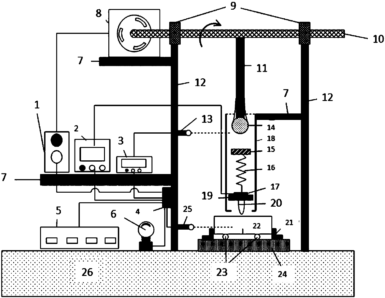
[0027] The schematic diagram of the overall structure of the brittle material crack prefabrication testing machine is as follows: figure 1 As shown, the whole includes base and support system, power output system, control system, limit protection, and sample fixture system. The support frame is made of high-strength steel, and the bearing 9 and the transmission shaft 10 are fixed on the top of the support frame 12. After the two ends of the bearing are kept horizontal, the transmission shaft of the left end bearing is connected with the motor 8, and the motor is fixed on the support plate connected to the support frame. superior. The support plate and the support frame are connected by flanges, and the motor and the support plate are connected by bolts. Two laser probes 13 and 25 with different functions are respectively connected to designated positions on the steel frame by bolts, and the upper and lower positions can be adjusted.

[0028] The limiting cylinder 18 is conne...


PUM


Abstract

The invention provides a brittle material fatigue crack prefabricating test machine. The test machine comprises a pedestal, a motor, a transmission shaft, an impact ball, a pressure head, a supportingframe, supporting plates, a laser counter, a pressure sensor, a laser signal controller, an alarm, a PLC control system, a compression spring, a limit barrel, a clamp and other parts. The loading ofdifferent sizes of load is realized through the pressure sensor by adjusting the position of the impact ball, a connecting rod and the limit cylinder to make the length of a prefabricated crack reacha required size, the PLC control system powers off the motor according to signal information fed back by a laser probe, and the alarm gives an alarm to prompt the completion of the prefabricating of the fatigue crack of a test piece. The test machine realizes unmanned guarding in the whole crack prefabricating process. The brittle material fatigue crack prefabricating test machine can greatly savemanpower and material resources, and also improves the crack preparation accuracy.

Description

technical field [0001] The invention relates to the field of testing material fracture toughness, in particular to a brittle material fatigue crack prefabrication testing machine. technical background [0002] Fatigue theoretical research has great engineering practical value. Its first function is to solve the problem of life determination, that is, to accurately estimate or predict the fatigue life of components, prevent catastrophic failure of structures, and avoid huge losses of life and property. The second function is to solve the problem of life extension, that is, to optimize materials and optimize processes to prolong the fatigue life of components, and to provide a basis for the development of new anti-fatigue materials. As we all know, it takes a lot of manpower, material and financial resources to test the fatigue performance of materials; especially the fatigue test of components and even full-scale structures under service loads is more expensive. Therefore, ...

Claims


Application Information

Patent Timeline
Patent Type & Authority Applications(China)
IPC IPC(8): G01N1/28
Inventor 梁文彦段志伟禾海伶王方鑫刘迁王振清
Owner HARBIN ENG UNIV
Why Eureka
Try Eureka