F200mm refrigeration-type infrared athermalization lens

A cooling type, lens technology, applied in cameras, projection devices, printing devices, etc., can solve the problems of increasing the volume and weight of the mechanical structure, poor adaptability to sudden changes in ambient temperature, and increasing the overall weight of the lens, etc. The effect of short lens structure length and quick assembly

Active Publication Date: 2018-01-19
FUJIAN FORECAM OPTICS CO LTD
View PDF6 Cites 2 Cited by
  • Summary
  • Abstract
  • Description
  • Claims
  • Application Information

AI Technical Summary

Problems solved by technology

However, the above methods mainly rely on the optical and thermal expansion characteristics of optical components and the thermal expansion properties of mechanical components to compensate for thermal defocus, which is highly dependent on the properties of the components themselves, poor adaptability to sudden changes i

Method used


Image

  • F200mm refrigeration-type infrared athermalization lens
  • F200mm refrigeration-type infrared athermalization lens
  • F200mm refrigeration-type infrared athermalization lens

Examples


Embodiment Construction

[0019] The present invention will be further described below in conjunction with the accompanying drawings and specific embodiments.

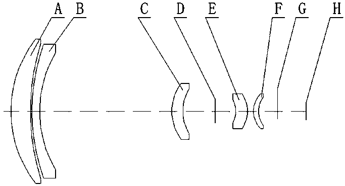
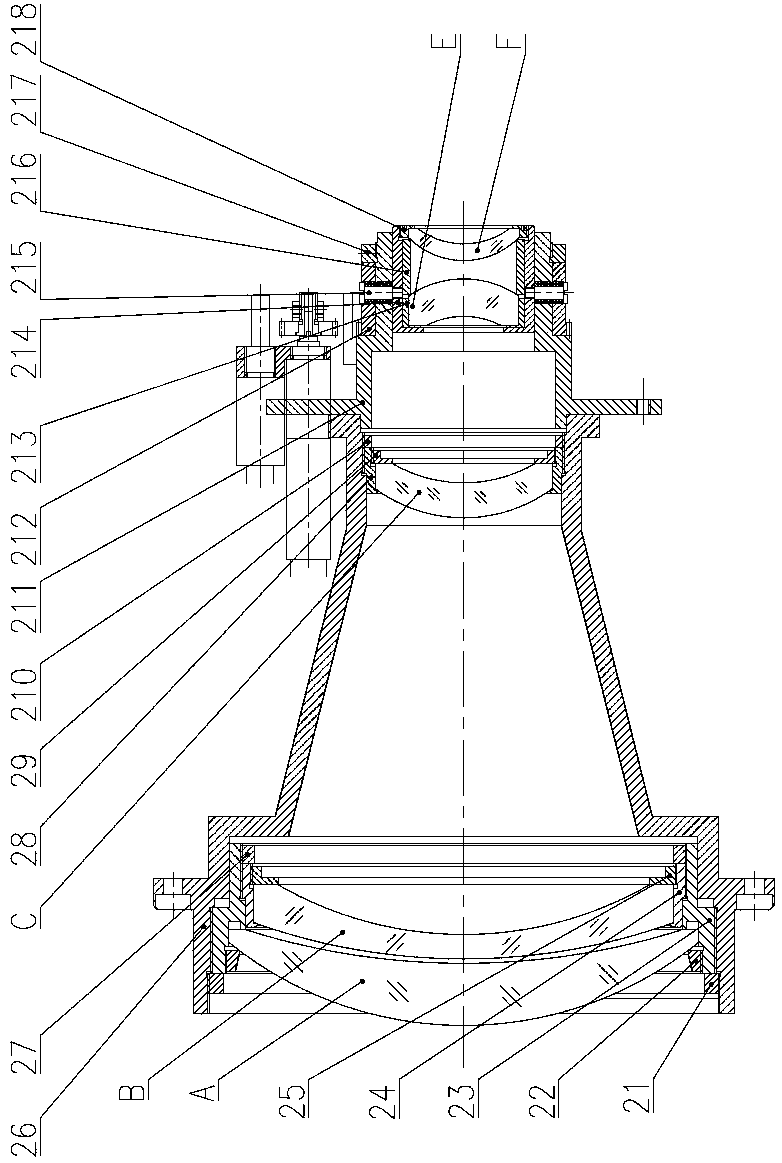
[0020] Such as Figure 1~3 As shown, a f200mm cooling type mid-wave infrared athermalization lens, the optical system of the lens is provided with a meniscus lens A with a positive dioptric power and a meniscus lens B with a negative dioptric power along the incident direction of the light from left to right. , positive power meniscus lens C, secondary imaging surface D, negative power meniscus lens E, positive power meniscus lens F, stop G, image plane H.

[0021] In this embodiment, the materials of the meniscus lens A with positive power, the meniscus lens E with negative power and the meniscus lens F with positive power are germanium; the meniscus lens B with negative power and the meniscus lens with positive power The material of the meniscus lens C is silicon.

[0022] In this embodiment, the air interval between the positive power meni...


PUM


Abstract

The invention relates to an f200mm refrigeration-type infrared athermalization lens, and the optical system of the lens is sequentially provided with a meniscus lens A with the positive focal power, ameniscus lens B with the negative focal power, a meniscus lens C with the positive focal power, a secondary imaging plane D, a meniscus lens E with the negative focal power, a meniscus lens F with the positive focal power, a diaphragm G and an image plane H from the left to the right along the light. The lens is small and exquisite in structure, achieves the athermalization through electromechanical focusing, and is high in stability. The impact on the lens from the environment factors is small, and the lens just employs two types of optical materials, thereby greatly reducing the productionand processing cost.

Description

technical field [0001] The invention relates to an f200mm cooling type mid-wave infrared athermalization lens. Background technique [0002] The working environment of the optical lens is not constant. The curvature, thickness, spacing and refractive index of the optical element will change with the change of the ambient temperature. At the same time, the focal power of the optical element will change. Thermal expansion and contraction will occur, and eventually the optical system will produce aberrations and thermal defocus, which will affect the imaging quality. [0003] In order to enable the optical lens to be used normally under complex ambient temperatures, it is necessary to perform athermalization on the optical system. Common infrared athermalization methods include optical athermalization, mechanical athermalization, and optical-mechanical athermalization. However, the above methods mainly rely on the optical and thermal expansion characteristics of optical elemen...

Claims


Application Information

Patent Timeline
IPC IPC(8): G02B13/14G02B13/18G02B1/00G02B7/04G03B13/34
Inventor 郑德键陈潇陶郅周阳黄剑峰
Owner FUJIAN FORECAM OPTICS CO LTD
Why Eureka
Try Eureka