Remote-sensing image target recognition method based on feature tensors and support tensor machine

A technology that supports tensor machines and remote sensing images. It is applied in the field of remote sensing image target recognition. It can solve the problem of unable to maintain the spatial structure information of remote sensing images, and achieve the effect of high practical value and good real-time performance.

Active Publication Date: 2018-01-19
HARBIN INST OF TECH
View PDF2 Cites 6 Cited by
  • Summary
  • Abstract
  • Description
  • Claims
  • Application Information

AI Technical Summary

Problems solved by technology

[0004] The purpose of the present invention is to solve the problem that the existing vector structure features cannot maintain the spatial structure information of the target itself in the remote sensing image, and the system model obtained from this training is difficult to directly meet the accuracy requirements. Target Recognition Method of Remote Sensing Image Based on Measuring Machine

Method used


Image

  • Remote-sensing image target recognition method based on feature tensors and support tensor machine
  • Remote-sensing image target recognition method based on feature tensors and support tensor machine
  • Remote-sensing image target recognition method based on feature tensors and support tensor machine

Examples


specific Embodiment approach 1

[0070] Specific implementation mode one: combine Figure 5 Describe this embodiment, the specific process of the remote sensing image target recognition method based on feature tensor and support tensor machine of this embodiment is:

[0071] Step 1. Select the training image set on the remote sensing image, and select the slices of the target to be recognized and the background sample on the training image according to the size of the target to be recognized on the training image. The size ratio of the circumscribed rectangle is 1.1-2;

[0072] For the recognition of aircraft targets, the original training images come from the GoogleEarth data source, and the recognition target is the KC135 tanker see figure 1 , according to the size of the recognition target, set the slice size to 70 pixels × 70 pixels, see target and background slices Figure 4a , Figure 4b , Figure 4c , Figure 4d , Figure 4e , Figure 4f , Figure 4g , Figure 4h , Figure 4i , Figure 4j , ...

specific Embodiment approach 2

[0083] Specific embodiment two: the difference between this embodiment and specific embodiment one is: extract the SIFT or SURF feature of slice in the described step 2, and build feature tensor; Process is:

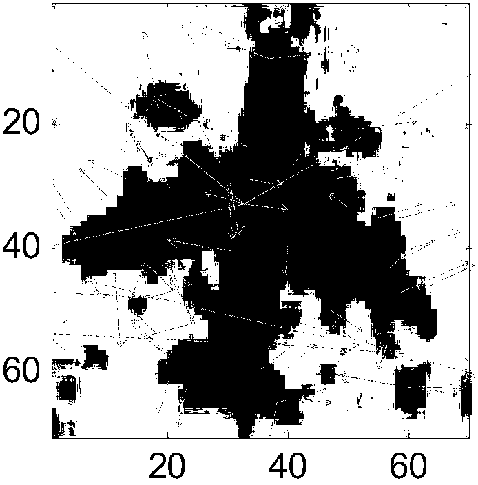
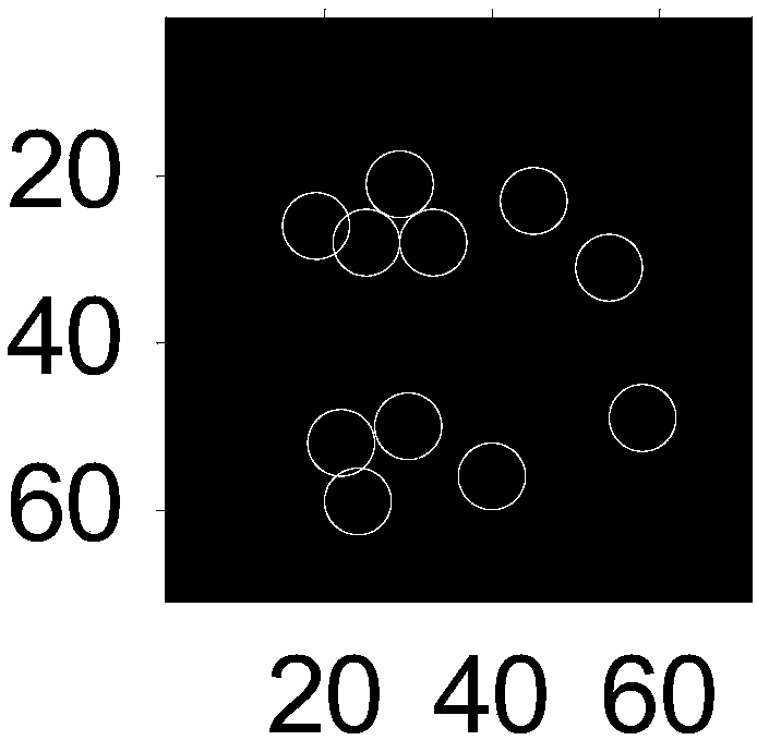
[0084] Step 21, extract the SIFT or SURF features of the slice, wherein the SIFT extraction results are shown in figure 2 , the starting point of the arrow is the feature point, which is the extracted SIFT or SURF feature. The direction of the arrow indicates the direction of the main gradient within the neighborhood of the feature point, and the longer the arrow, the larger the response of the main gradient direction. SURF feature extraction results see image 3 , the circles in the figure represent the positions of SURF feature points on the slice. In order to better maintain the spatial structure of the data, according to the SIFT or SURF features of the slice, a fifth-order feature tensor is established. The first and second order of the feature tensor represent t...

specific Embodiment approach 3

[0140] Specific embodiment three: the difference between this embodiment and specific embodiment one or two is: the optimization process of the objective function to be optimized in the step three is:

[0141] Step 1): Initialize the parameters of the objective function to be optimized Alpha[i]=0, i=1, 2,..., N, b 0 = 0,

[0142] Among them, Alpha is the Lagrangian multiplier that supports the optimization objective function of the tensor machine. In order to reduce the amount of calculation, the projection vector W is optimized by optimizing Alpha. iter-1 , b 0 As the offset, it supports a collection of tensor sequences

[0143] Step 2): iter=1, η iter =1 / (iter+1);

[0144] Where iter is the number of iterations, η iter is the learning rate;

[0145] Step 3): Randomly select a feature tensor from the feature tensor constructed in step 2, set its subscript as t, t represents the tth feature tensor, and the value of t is 1 to N, and X is obtained t , X t is the tth fe...


PUM


Abstract

The invention relates to a remote-sensing image target recognition method based on feature tensors and a support tensor machine, and aims to solve the problem that existing vector structure features cannot maintain spatial structure information which targets in remote-sensing images have, and system models trained and obtained thereby are very difficult to directly satisfy precision requirements.A process of the method includes: first, selecting a training image set on remote-sensing images, and selecting slices of to-be-recognized target and background samples on training images according tothe size of to-be-recognized targets on the training images; second, extracting SIFT or SURF features of the slices, and constructing the feature tensors; third, deriving a classification decision hyperplane; fourth, utilizing the support tensor machine to carry out target recognition on a to-be-recognized remote-sensing image to obtain slices containing objects labeled as the targets; and fifth,extracting the slices containing the objects labeled as the targets, and carrying out slice merging to obtain a final recognition result. The method is used in the field of remote-sensing image target recognition.

Description

technical field [0001] The invention relates to a remote sensing image target recognition method. Background technique [0002] With the development of remote sensing technology, various resolutions of remote sensing technology are improving, but this has caused the overall data volume of remote sensing images to increase. These remote sensing images with a large amount of data have provided a lot of help to scientific research workers, national production departments and commercial organizations. However, the low efficiency of traditional artificial information processing has become a bottleneck for the further development of remote sensing data processing technology. In this case, how to process remote sensing image data quickly, accurately and efficiently is an important direction for the development of remote sensing technology. Faced with this situation, intelligent information extraction and processing has become particularly important. Most of the objects studied i...

Claims


Application Information

Patent Timeline
Patent Type & Authority Applications(China)
IPC IPC(8): G06K9/00G06K9/46G06K9/62
Inventor 陈浩高通任卿龙赵静
Owner HARBIN INST OF TECH
Why Eureka
Try Eureka