Packaging structure of fuel cell stack

A fuel cell stack and packaging structure technology, applied to fuel cells, circuits, electrical components, etc., can solve the problems of inconsistent reaction efficiency, uneven internal resistance of the stack body, affecting the service life, etc., to ensure normal working conditions, convenient The effect of automated production and increased service life

Pending Publication Date: 2018-01-19
中氢新能源科技(深圳)有限公司
View PDF5 Cites 13 Cited by
  • Summary
  • Abstract
  • Description
  • Claims
  • Application Information

AI Technical Summary

Problems solved by technology

[0004] At present, the packaging structure of the fuel cell stack cannot guarantee uniform and constant assembly pressure, so that the normal operation of the stack body cannot be guaranteed, which affects its service life. One of the reasons is that there is a contact resistance between the stack body and the collector plate. If the pressure is not uniform , will lead to uneven contact resistance, which in turn will cause uneven internal resistance of each point inside the stack body and inconsistent reaction efficiency, resulting in inconsistent heat generation everywhere, easy to cause local overheating, and damage the stack body. If the pressure is not constant, then The volt-ampere characteristics of the battery are unstable, which leads to a decrease in the matching with the parameters of the fuel cell stack control software, and the optimal control cannot be achieved
The second reason is that both the stack body and the collector plate have their maximum stress. Excessive local pressure may cause damage to the stack body and gas leakage.

Method used


Image

  • Packaging structure of fuel cell stack
  • Packaging structure of fuel cell stack

Examples


Embodiment

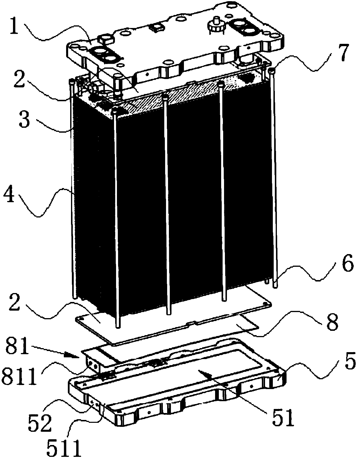
[0023] Embodiment: a packaging structure of a fuel cell stack, such as Figure 1-Figure 2 As shown, it includes an upper end plate 1, an insulating plate 2, a collector plate 3, a stack body 4 and a lower end plate 5, the upper end plate 1 and the lower end plate 5 are parallel to each other, and the upper end plate 1 and the lower end plate 5, two insulating plates 2 are arranged between them, two collector plates 3 are arranged between the two insulating plates 2, and the stack body is arranged between the two collector plates 3 4;

[0024] It also includes several insulating fixing rods 6 located on the periphery of the stack body, the two ends of the insulating fixing rods 6 are respectively connected to the nuts 7 of the upper end plate 1 and the nuts 7 of the lower end plate 5, and the nuts of the nuts 7 The inner surface has internal threads matching the external threads at both ends of the insulating fixing rod 6;

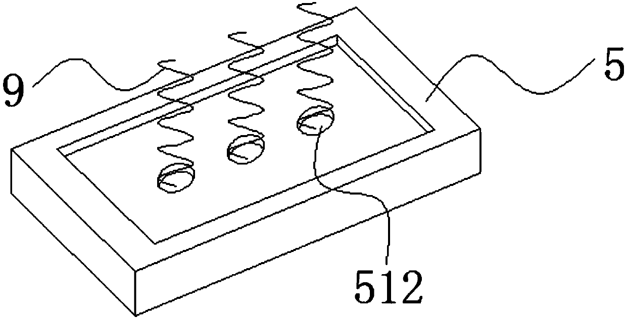
[0025] The upper surface of the lower end plate 5 h...


PUM

PropertyMeasurementUnit
lengthaaaaaaaaaa
lengthaaaaaaaaaa

Abstract

The invention discloses a packaging structure of a fuel cell stack. The packaging structure comprises an upper end plate, insulating plates, current collection plates, a stack body and a lower end plate, wherein the upper end plate and the lower end plate are parallel to each other; the two insulating plates are arranged between the upper end plate and the lower end plate; the two current collection plates are arranged between the two insulating plates; the stack body is arranged between the two current collection plates; the packaging structure further comprises a plurality of insulating fixed rods which are located at the periphery of the stack body; the two ends of the insulating fixed rods are connected with a nut of the upper end plate and a nut of a lower end plate respectively; inner surfaces of the nuts are provided with inner threads which are matched with outer threads at the two ends of the insulating fixed rods; the upper surface of the lower end plate is provided with a concave groove and an elastic supporting part located between the groove and the insulating plates; the groove is parallel to the surface of the lower end plate. The packaging structure disclosed by theinvention provides uniform and constant assembling pressure to the inner part of the cell stack, so that the stress on the lower surface of the stack body is uniform; normal working conditions of thecell stack is ensured and the service life of the cell stack is prolonged.

Description

technical field [0001] The invention belongs to the technical field of battery packaging structures, and in particular relates to a packaging structure of a fuel cell stack. Background technique [0002] In today's global energy shortage and high oil prices, it is imperative to find new energy as a substitute for fossil fuels. Fuel cells are considered to be the fourth-generation power generation technology after hydropower, thermal power and atomic power generation. It directly converts the chemical energy of oxidants and reductants into electrical energy through electrocatalytic reactions. It is an efficient, safe, clean and flexible new type of power generation technology. power generation technology. Among them, the proton exchange membrane fuel cell has a wide range of application prospects in ground power stations, electric vehicles and portable power sources due to its remarkable advantages such as high efficiency, high energy density, low reaction temperature, no no...

Claims


Application Information

Patent Timeline
Patent Type & Authority Applications(China)
IPC IPC(8): H01M8/247H01M8/248
CPCY02E60/50
Inventor 邱耀弘夏泮文张骞为徐国兵
Owner 中氢新能源科技(深圳)有限公司
Why Eureka
Try Eureka