
Solar panel Fault detection method and system and robot

A solar panel and fault detection technology, applied in the field of solar panels, can solve problems such as difficulty in accurately judging the location of the fault area, and difficulty in finding out the circuit fault of the solar panel in time.

Active Publication Date: 2018-01-19
SUZHOU RADIANT PHOTOVOLTAIC TECH
View PDF6 Cites 8 Cited by
  • Summary
  • Abstract
  • Description
  • Claims
  • Application Information

AI Technical Summary

Problems solved by technology

[0004] The purpose of the present invention is to provide a solar panel fault detection method and system to solve the technical problems in the prior art that it is difficult to detect the circuit fault of the solar panel in time and the location of the fault area is difficult to accurately judge

Method used


Image

  • Solar panel Fault detection method and system and robot
  • Solar panel Fault detection method and system and robot
  • Solar panel Fault detection method and system and robot

Examples


Embodiment 1

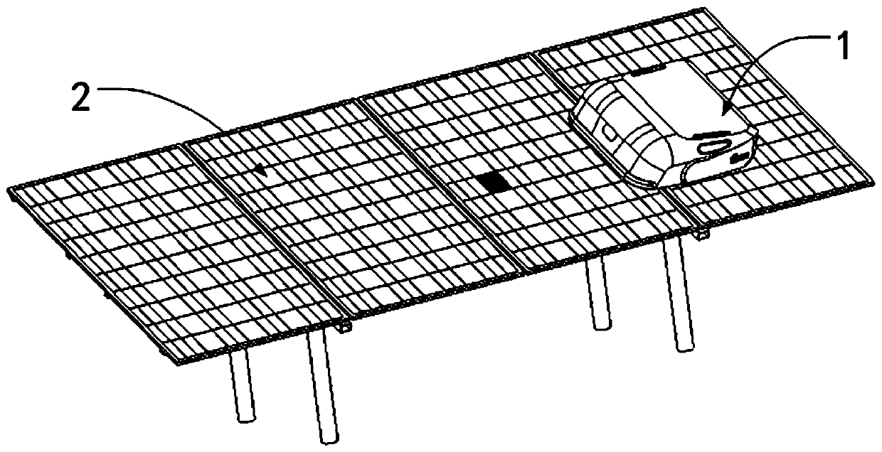
[0041] Such as figure 1As shown, Embodiment 1 provides a robot 1 traveling or stopping on a solar panel 2 , which includes a solar panel fault detection system 3 . The robot 1 includes a control system and a power system, a solar panel failure detection system 3, the power system is connected to the control system, and the control system is used to control the power system to drive the robot 1 to travel on the solar panel 2, and Used to control the solar panel fault detection system3.

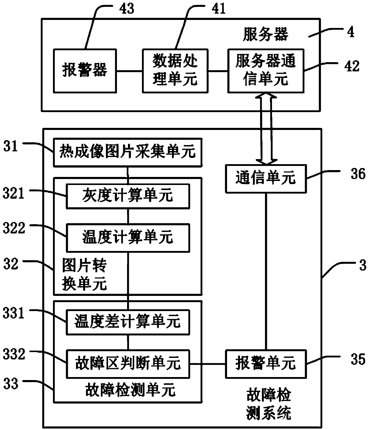
[0042] Such as figure 2 As shown, in this embodiment, the solar panel fault detection system 3 includes a thermal imaging image acquisition unit 31 , an image conversion unit 32 , and a fault detection unit 33 arranged in a processor.

[0043] The thermal imaging picture acquisition unit 31 includes a thermal imaging camera, the central axis of the lens has a certain angle with respect to the solar panel, and acquires a thermal imaging picture of a certain area of ​​the solar panel at regula...

Embodiment 2

[0062] Such as Figure 6 As shown, the solar panel fault detection system described in Embodiment 2 includes all the technical solutions of the solar panel fault detection system described in Embodiment 1. The difference between the two is that in Embodiment 2, the solar panel fault detection system 3 also includes A failure area identification unit 34 is included.

[0063] The fault area identification unit 34 is used to identify the position of the fault area. The fault area identification unit 34 includes a real-time picture collection unit 341 , a picture integration unit 342 , and a fault area calculation unit 343 .

[0064] The real-time picture collection unit 341 is an ordinary optical camera, which is used to obtain real-time pictures of the sampling area on the upper surface of the solar panel 2. During the advancing process of the cleaning robot, one picture is taken at regular time intervals, thereby obtaining various areas on the entire solar panel. real-time ima...


PUM


Abstract

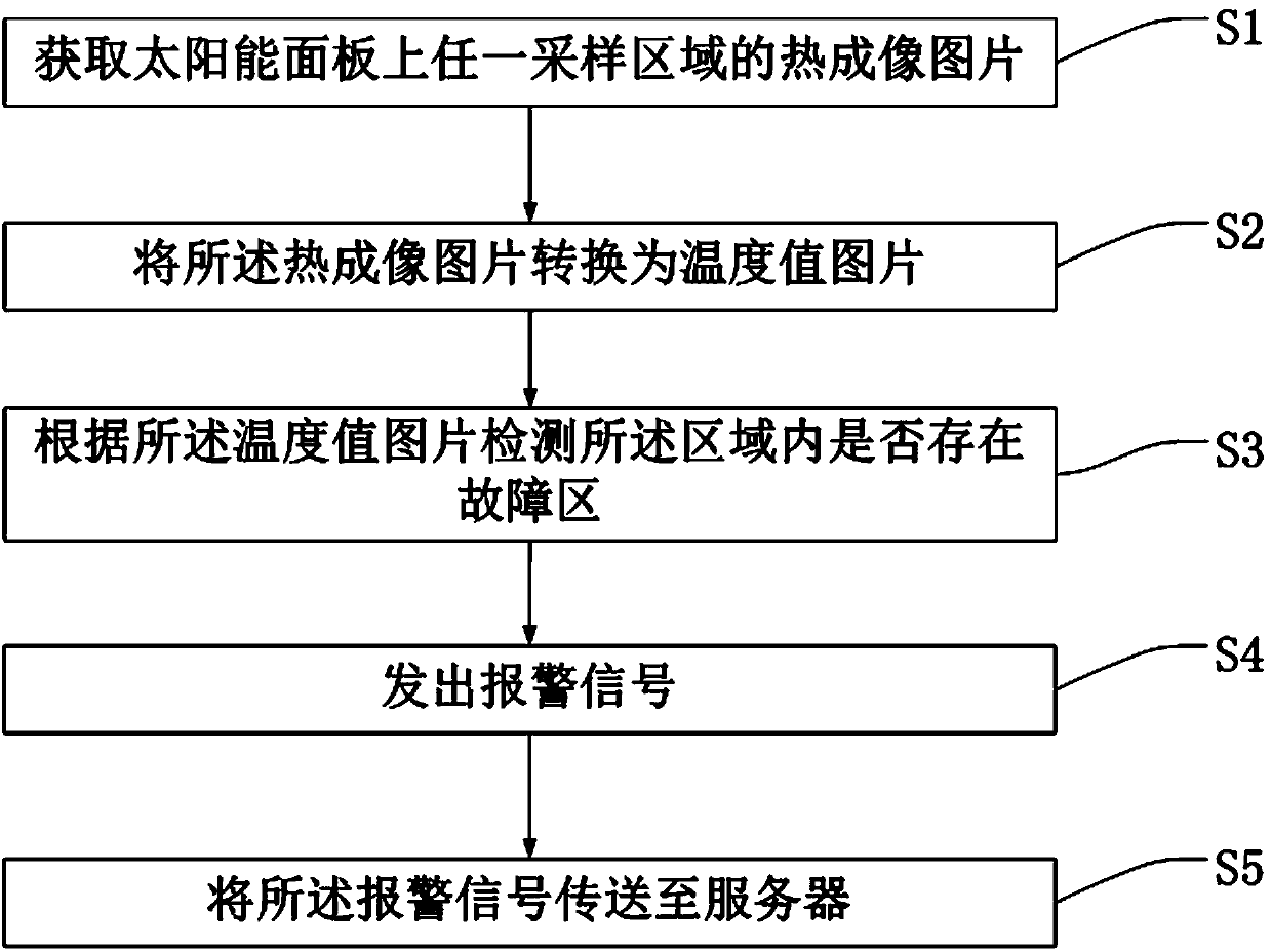
The invention discloses a solar panel fault detection method and system and a robot. The method comprises the following steps that 1, a thermal imaging picture of any sampling area on the solar panelis acquired; 2, the thermal imaging picture is converted into a temperature value picture; 3, according to the temperature value picture, whether or not a fault area exists in the area is detected. Byadopting a thermal imaging technology, the temperature conditions of the solar panel on all areas are detected when the sweeping robot walks, an area with extremely high temperature is judged into the fault area, the system gives an alarm to a background server in time and informs maintenance, so that the operation safety of the solar panel is guaranteed, and the fault area of the solar panel isprevented from being further enlarged.

Description

technical field [0001] The invention relates to the fields of solar panels and the like, in particular to a solar panel fault detection method and system and a robot. Background technique [0002] A solar panel refers to a panel that uses the photovoltaic effect (photovoltaic) that occurs under light conditions to convert solar energy directly into electrical energy. It is the most direct of many solar energy utilization methods. At present, most solar panels are made of single crystal. silicon. Since electricity can be generated wherever the sun shines, solar photovoltaics are used in everything from large power stations to small portable chargers. [0003] During the use of the solar panel, there may be a problem that the local circuit of the solar panel is damaged, especially when the circuit nodes of the solar panel are damaged. When damaged, the panel is likely to be normal in appearance and difficult to discern with the naked eye. If the faulty node cannot be repair...

Claims


Application Information

Patent Timeline
Patent Type & Authority Applications(China)
IPC IPC(8): H02S50/10G01J5/10
CPCY02E10/50
Inventor 彭芳徐建荣徐斐王佳庆
Owner SUZHOU RADIANT PHOTOVOLTAIC TECH
Learn More