High water pressure precipitation well structure in metro station foundation pit and still water grouting blocking method

A technology for subway stations and dewatering wells, which is applied in infrastructure engineering, protection devices, buildings, etc., can solve the problems of rising water level in dewatering well pipes, difficulty in plugging construction, and groundwater pouring into foundation pits, and achieves novel methods and applicable scope. Wide, safe and reliable construction effect

Inactive Publication Date: 2018-01-23
CHINA RAILWAY 12TH BUREAU GRP +1
View PDF5 Cites 10 Cited by
  • Summary
  • Abstract
  • Description
  • Claims
  • Application Information

AI Technical Summary

Problems solved by technology

[0005] Adding cotton wool and other things, then pouring concrete, and finally closing the cover plate, the process operation is relatively complicated; at the same time, because the top of the dewatering well in the above project moves down continuously with the excavation of earthwork, after the construction of the waterproof bottom plate of the building is completed, the height of the top of

Method used


Image

  • High water pressure precipitation well structure in metro station foundation pit and still water grouting blocking method
  • High water pressure precipitation well structure in metro station foundation pit and still water grouting blocking method
  • High water pressure precipitation well structure in metro station foundation pit and still water grouting blocking method

Examples


Embodiment

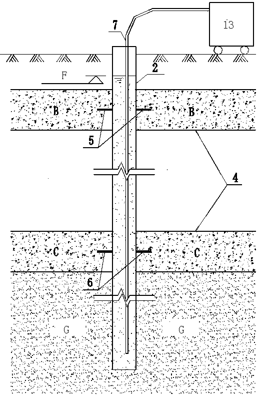
[0044] The construction of the high water pressure dewatering well plugging in the foundation pit of the Ice and Snow World Station of Harbin Metro Line 2 undertaken by our company uses the hydrostatic grouting method described in the present invention to construct the foundation pit in a stratum with high water pressure and high water level. The decompression well uses the main structure and the dewatering well pipe to form a closed space. After stopping the pumping, the water level rises automatically to balance the formation and the water pressure inside and outside the dewatering well to form still water and complete the grouting plugging. The specific methods are as follows:

[0045] Design of decompression well structure: When designing the decompression and dewatering well in the foundation pit, optimize the structure and form of the well pipe, and use the main structure and the dewatering well pipe to form a closed space to ensure that the pumping is stopped later, the w...


PUM


Abstract

The invention relates to the field of metro station foundation pit confined aquifer precipitation, in particular to a high water pressure precipitation well structure in a metro station foundation pitand a still water grouting blocking method, and the problem about blocking of a precipitation well under the situation of high water pressure is solved. The high water pressure precipitation well structure comprises a well pipe in the metro station foundation pit, the well pipe is a closed steel pipe, the top elevation of the well pipe is larger than that of the natural water level, the well pipepenetrates a bottom plate and a top plate of a station body, and a water pump is arranged in the well pipe. The still water grouting blocking method for the high water pressure precipitation well inthe metro station foundation pit is provided. A closed space is formed through a body structure and the precipitation well pipe, the water level is automatically elevated after water pumping is stopped, the pressure of the stratum and the water pressure inside and outside the precipitation well are balanced, still water is formed, grouting blocking is conduced, the method is novel, and construction is safe and reliable. The high water pressure precipitation well structure and the still water grouting blocking method are suitable for blocking of all precipitation wells, but the advantages in blocking of large water pressure and high water level shallow water or confined water precipitation wells are obvious, the technology is advanced, the application range is wide, practicability is high,and the popularization prospects are good.

Description

technical field [0001] The invention relates to the field of dewatering of a pressurized aquifer in a foundation pit of a subway station, in particular to a structure of a high water pressure dewatering well in a foundation pit of a subway station and a hydrostatic grouting sealing method. Background technique [0002] With the rapid development of urbanization, rail transit and high-rise buildings are becoming more and more popular, and the construction of deep foundation pits will become a normal trend. In these projects, the treatment of groundwater is the first problem to be faced. Due to the dewatering requirements of the confined aquifer in the foundation pit or the anti-surge demand of the base, the decompression and dewatering well in the foundation pit is already a common way of dewatering, but often under high water head pressure, the plugging of the high water pressure dewatering well is another problem. In the later period, how to solve the blockage problems suc...

Claims


Application Information

Patent Timeline
IPC IPC(8): E02D19/10E02D15/04E02D31/02
Inventor 王海乔国强赵策张利强刘建徐加飞赵香萍李晓
Owner CHINA RAILWAY 12TH BUREAU GRP
Why Eureka
Try Eureka