

Method and device for measuring contact force of pantograph and catenary
A measurement method and a technology of a measurement device, which are applied in the measurement of the change force of the optical properties of the material when it is stressed, can solve the problems of complex experimental devices and many installation restrictions, and achieve good anti-interference and measurement The effect of small error and simple installation of equipment
- Summary
- Abstract
- Description
- Claims
- Application Information
AI Technical Summary
Problems solved by technology
Method used
Image

Examples
Embodiment 1
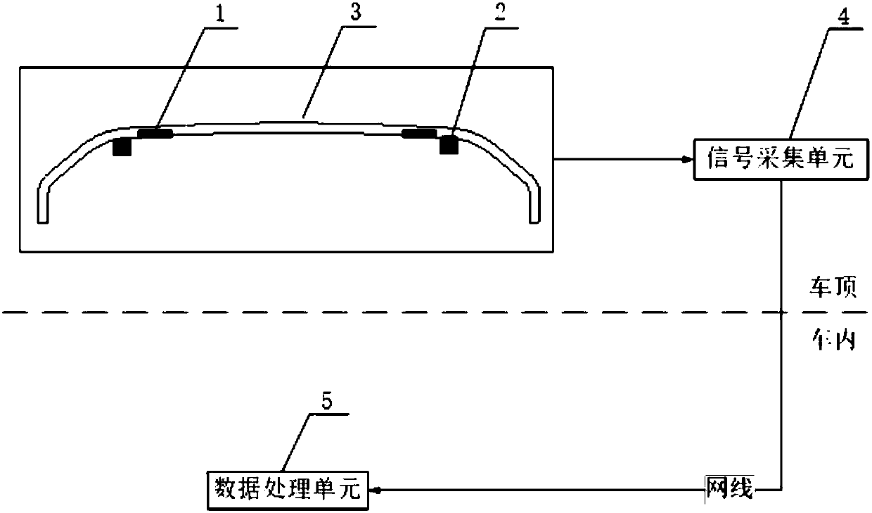
[0028] now attached figure 1 The present invention is further described.
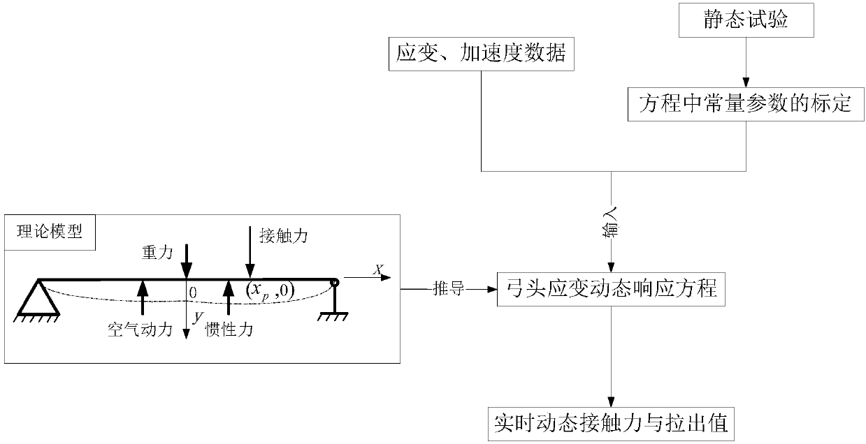
[0029] A pantograph-catenary contact force measurement method is to regard the pantograph head as a beam model, and derive the dynamic response equation of the bow head strain,
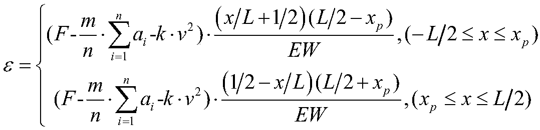
[0030] The bow head strain dynamic response equation is as follows:
[0031]
[0032] In the formula: ε is the longitudinal strain of the pantograph slide, which is measured by the strain sensor; F is the contact force between the pantograph and the catenary; m is the sprung mass of the bow head. In this embodiment, the TSG22 pantograph is used, and m=4.8 kg; a i Is the acceleration of the ith acceleration sensor at the bottom of the slide plate, which is measured by the acceleration sensor; n is the number of acceleration sensors, and in this embodiment n=2; k is the aerodynamic proportional coefficient, where k=0.00228; v is the train running speed, x p is the abscissa of the position of the contact point; x is the abs...
PUM
 Abstract
Description
Claims
Application Information