Flying probe tester movement shaft positioning precision test system and test method thereof

A flying probe testing machine and positioning accuracy technology, applied in the direction of electronic circuit testing, etc., can solve the problems of low test efficiency and test accuracy, achieve the effects of improving dimming efficiency and test efficiency, ensuring operability, and improving test efficiency

Active Publication Date: 2018-01-23
HANS CNC SCI & TECH
View PDF5 Cites 6 Cited by
  • Summary
  • Abstract
  • Description
  • Claims
  • Application Information

AI Technical Summary

Problems solved by technology

[0005] Based on this, it is necessary to provide a testing system and a testing method for the positioning accuracy of the moving axis of the flying probe testing machine in view of the problem of low testing efficiency and testing accuracy of the positioning accuracy of the moving axis of the flying probe testing machine

Method used


Image

  • Flying probe tester movement shaft positioning precision test system and test method thereof
  • Flying probe tester movement shaft positioning precision test system and test method thereof
  • Flying probe tester movement shaft positioning precision test system and test method thereof

Examples


Embodiment Construction

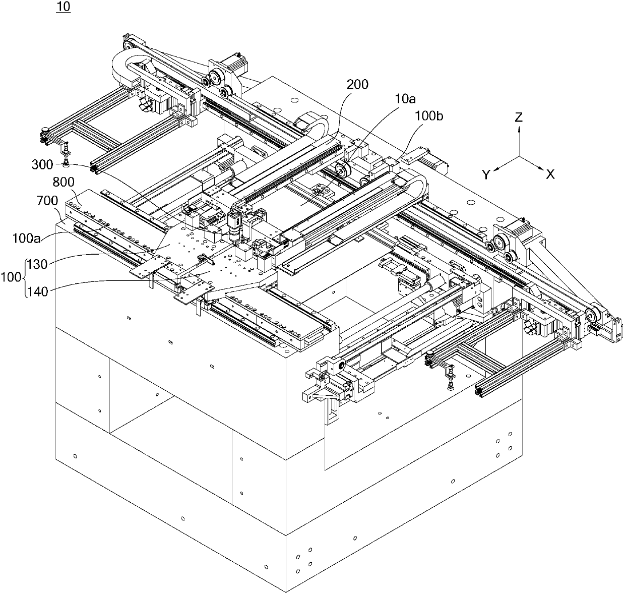
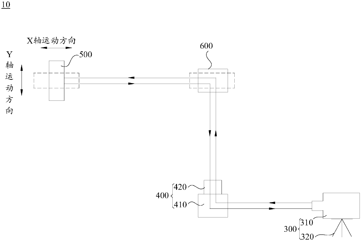
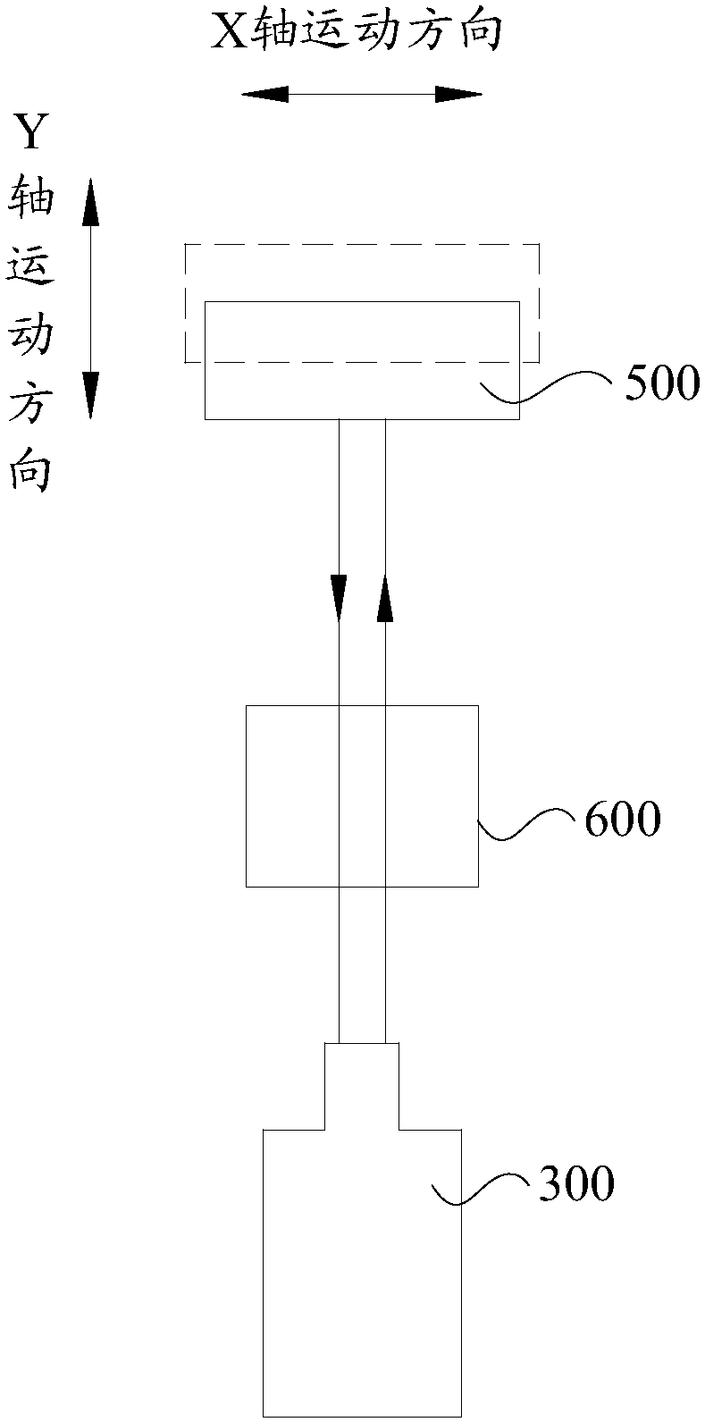
[0046] In order to facilitate the understanding of the present invention, the testing system and the testing method for the positioning accuracy of the moving shaft of the flying probe tester will be described in a more comprehensive manner with reference to the relevant drawings. The first embodiment of the testing system and testing method for the positioning accuracy of the moving shaft of the flying probe tester is shown in the accompanying drawings. However, the testing system and testing method for the positioning accuracy of the moving shaft of the flying probe tester can be implemented in many different forms and are not limited to the embodiments described herein. On the contrary, the purpose of providing these embodiments is to make the disclosure of the testing system and the testing method for the positioning accuracy of the moving axis of the flying probe tester more thorough and comprehensive.

[0047] It should be noted that when an element is referred to as being ...


PUM


Abstract

The invention relates to a flying probe tester movement shaft positioning precision test system and a test method thereof. The flying probe tester movement shaft positioning precision test system comprises a laser assembly, an angle turning lens group, a reflector group and a single light splitter group. The laser assembly is used for generating a laser beam; the angle turning lens group is used for propagating the laser beam; the reflector group is used for reflecting the laser beam to enable the laser beam to be reflected back into the laser assembly; and the single light splitter group is sued for propagating the laser beam. The flying probe tester movement shaft control method and positioning precision compensation method ensures that a flying probe tester has higher test precision, thereby solving the problem of low test precision of the flying probe tester. Besides, the flying probe tester movement shaft positioning precision compensation method is easy to operate and low in cost.

Description

Technical field [0001] The invention relates to the technical field of testing of printed circuit boards, in particular to a testing system and a testing method for the positioning accuracy of a moving shaft of a flying probe testing machine. Background technique [0002] The flying probe tester includes X-axis motion axis and Y-axis motion axis. Probes driven by motors are installed on both X-axis and Y-axis motion axes. The probes are driven by the corresponding motors to move in the Z-axis direction. To make contact with the solder joints on the printed circuit board to perform electrical measurements on the printed circuit board. Due to the functional requirements of the flying probe tester, the two ends of the Y-axis motion axis are respectively erected on the two X-axis motion axes, and the distance between the two ends of the Y-axis motion axis is relatively large, and the Y-axis motion axis is installed on the X axis by two The motor of the motion axis is driven or drive...

Claims


Application Information

Patent Timeline
Patent Type & Authority Applications(China)
IPC IPC(8): G01R31/28
Inventor 谭艳萍王星翟学涛杨朝辉高云峰
Owner HANS CNC SCI & TECH
Why Eureka
Try Eureka