Chuck, stepped jaw, and machine tool

A chuck and claw technology, applied in the field of chuck mechanism, can solve problems such as processing obstacles, efficiency reduction, and complicated operations, and achieve the effect of low possibility, high efficiency, and rapid removal

Inactive Publication Date: 2018-01-23
有限会社新沙泰克
View PDF7 Cites 7 Cited by
  • Summary
  • Abstract
  • Description
  • Claims
  • Application Information

AI Technical Summary

Problems solved by technology

However, in the conventional chuck mechanism, a relatively large countersink hole for inserting bolts is formed on the top of the soft jaw or the main jaw, and chips generated during cutting, etc., enter the countersink hole, and there will be future The risk of processing disorders
[0008] In addition, when workpiece processing using a machine tool is desired to be performed extremely efficiently in order to directly affect the product cost, in the conventional chuck mechanism, a workpiece is usually grasped by three soft jaws, because one soft jaw is composed of two soft jaws. Each mounting bolt is installed on the main jaw, so in order to replace the soft jaw, it is necessary to dismantle the bolts 6 times and install them 6 times, a total of 12 bolts, which makes the work complicated and reduces the efficiency.

Method used


Image

  • Chuck, stepped jaw, and machine tool
  • Chuck, stepped jaw, and machine tool
  • Chuck, stepped jaw, and machine tool

Examples


no. 1 approach

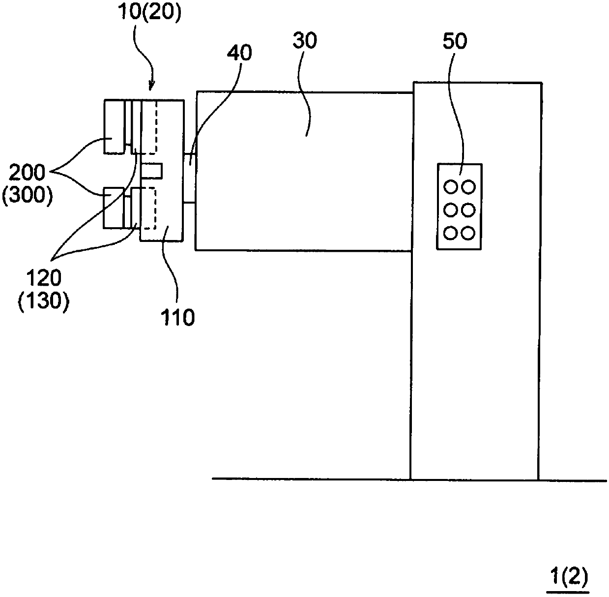
[0043] refer to Figure 1 ~ Figure 1 3. Describe the first embodiment of the present invention. In this embodiment, a lathe to which the guide jaw and chuck mechanism of the present invention is applied will be described as an example of the machine tool of the present invention. In addition, in the description of each of the following embodiments including the first embodiment, the same reference numerals are assigned to the same or similar configurations, and descriptions repeated in each embodiment will be omitted. Such as figure 1 As shown, the lathe 1 of this embodiment has: a chuck mechanism 10 for gripping a workpiece to be processed; a motor 30 for rotationally driving the chuck mechanism 10; and a control unit 50 for controlling the transmission of the rotational power of the motor 30 to the chuck. The spindle (spindle) 40 of the disk mechanism 10, the motor 30, and the like.

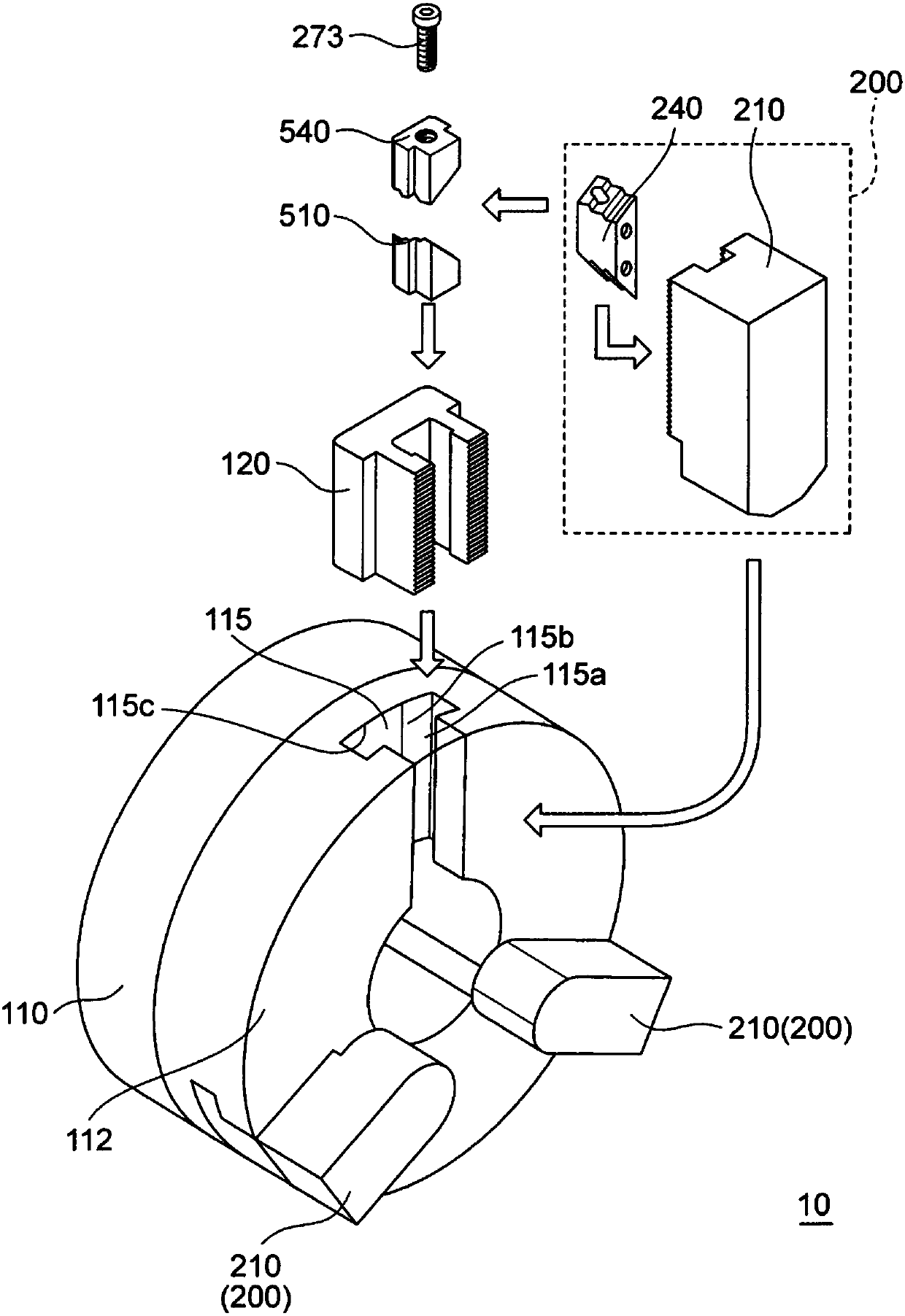
[0044] Such as figure 2 As shown, the chuck mechanism 10 has a cylindrical chuck body ...

no. 2 approach

[0093] main reference Figure 14 ~ Figure 17B , to describe the second embodiment of the present invention. The lathe 2 of the second embodiment (refer to figure 1 ) means that the structure of the main jaw, guide jaws, and clamps of the chuck mechanism 20 is different from that of the chuck mechanism 10 of the lathe 1 of the first embodiment.

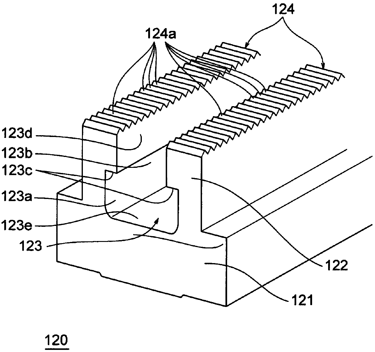
[0094] Such as Figure 14 As shown, the main jaw 130 is different from the main jaw 120 of the first embodiment in the structure of the serrated surface 134 on both sides of the claw setting groove 123 . Such as Figure 14 As shown, the sawtooth pattern formed on the sawtooth surface 134 of the main jaw 130 is a structure in which a plurality of square tapered spikes 134a are arranged. The cross-sectional shape of each spike 134a is substantially triangular, and each spike 134a has a chamfered front end and four slopes inclined from the front end.

[0095] The spikes 134a are arranged at predetermined intervals in the extending di...

no. 3 approach

[0114] refer to Figure 18A ~ Figure 19C , the third embodiment of the present invention will be described. Such as Figure 18A , Figure 18B As shown, in the guide claws 200b, 300b of the third embodiment, the U-shaped grooves 265, 365 opened at the bottom are formed in the guides 240b, 340b instead of fastening bolt passing holes. Figure 18A It is a guide claw 200b showing a third embodiment in which a fastening bolt passing U-shaped groove 365 is formed in a guide 240 with respect to the guide claw 200 of the first embodiment, Figure 18B It shows the guide claw 300b of the third embodiment in which the U-shaped groove 365 for fastening bolt passing is formed in the guide 340 with respect to the guide claw 300 of the second embodiment.

[0115] The guide claws 200 and 300 of the above-mentioned first and second embodiments pass the fastening bolts 273 through the fastening bolt passing holes 263 and 363 formed in the guides 240 and 340, and hold the guides 240 and 340 b...


PUM


Abstract

The invention provides a jaw that can be efficiently replaced, and that allows machining defects to be prevented. A stepped section 240 having a planar trapezoid shape and having an undulating engagement surface formed on two end surfaces 245, 246 is installed on the lower surface of a soft jaw 210 to form a stepped jaw 200. In a jaw installation groove 123 of a master jaw 120, the stepped section240 is gripped from both radial sides by a pair of grips 510, 540; and the stepped section 240 is pulled in towards the bottom of the jaw installation groove 123. The radial position of the soft jaw310 is defined by an engagement between serration surfaces 124, 234 on the lower surface of the soft jaw 310 and the upper surface of the master jaw 120. The tangential position of the soft jaw 310 isdefined by close contact of the stepped section 240 with the side surface of the jaw installation groove 123 that constitutes the base side of an isosceles trapezoid. The stepped jaw 300 and the grips 510, 540 are linked and fastened by a single clamp bolt 273. The stepped section 240 is linked to the soft jaw 310 from the lower surface; and no counterbores, etc., are present on the upper surface.

Description

technical field [0001] The present invention relates to a chuck mechanism for gripping a workpiece (work object) and fixing it to a working machine such as a lathe, a guide claw used for the chuck mechanism, and a working machine having the chuck mechanism and the guide claw. Background technique [0002] In the chuck mechanism of a machine tool such as a lathe (for example, refer to Patent Document 1), in order to perform high-precision machining of a workpiece, it is necessary to align the workpiece with high precision and / or to reproduce the height when the workpiece is reinstalled after being removed once. Workpiece alignment etc. As a chuck that can meet this requirement, a chuck mechanism has also been proposed, in which a plurality of zigzags extending in different directions are formed in advance on the abutting surface of the main jaw and the soft jaw. These zigzags are engaged to prevent the soft jaw from shifting in the surface direction of the contact surface wi...

Claims


Application Information

Patent Timeline
Patent Type & Authority Applications(China)
IPC IPC(8): B23B31/10B23Q11/08
CPCB23Q11/08B23B31/001B23B2260/056B23B2260/136Y10T279/1993Y10T279/1986B23B31/102B23B31/16279B23B2231/28B23B2231/342
Inventor 石川祯章
Owner 有限会社新沙泰克
Why Eureka
Try Eureka