Foaming forming mechanical equipment

A kind of mechanical equipment and foam molding technology, which is applied to household components, applications, household appliances, etc., can solve problems such as increased energy consumption, inability to adapt to industrial production application requirements, and unsatisfactory heating and cooling speeds, so as to increase production capacity and increase Effect of water recovery and utilization rate, energy consumption reduction

Pending Publication Date: 2018-01-26
张春花
0 Cites 5 Cited by

AI-Extracted Technical Summary

Problems solved by technology

In order to overcome the above problems, people began to develop heating and cooling process molding equipment at the same station, which has greatly improved the number of workers, labor intensity and environmental protec...

Method used

As preferably, described frame 1 is a three-channel structure, and the quantity of described mold heating station 2, mold output station 3, mold cooling station 4 is two and correspondingly arranged, respectively with two The mold supporting bracket 14 corresponding to the channel works simultaneously under the drive of the lifting cylinder 9, which further improves the production capacity and production efficiency.
Foam molding mechanical equipment of the present invention is heating, cooling procedure integral molding machine, and the heating and cooling procedure in EVA foaming process can be carried out simultaneously, can save labor force and improve production capacity greatly; Utilize superconducting electromagnetic heating to mention present The steam heating method in the prior art greatly improves the heating speed; in terms of cooling, the foaming mold 18 after foaming is cooled by usin...

Abstract

The invention relates to foaming forming mechanical equipment. The foaming forming mechanical equipment comprises a machine frame. A mold heating station, a mold output station and a mold cooling station are sequentially arranged on the machine frame from top to bottom in a layered mode. A superconducting heating plate used for heating a foaming mold is arranged in the mold heating station. The mold cooling station is internally provided with an atomizing cooling plate used for cooling the foaming mold. A mold outlet oil cylinder used for driving the foaming mold to be output is arranged on the side edge of the mold output station. The foaming forming mechanical equipment further comprises a mold exchange frame used for conveying the foaming mold, and a lifting oil cylinder used for driving the mold exchange frame to move up and down. The mold exchange frame is provided with a mold conveying motor used for conveying the foaming mold. The heating speed is greatly increased by adopting superconducting heating, the cooling speed is increased by adopting the atomizing cooling plate, the productivity is increased advantageously, the manpower can be saved, energy consumption can be reduced, and the effects that the water source recovery and utilization rate is increased, energy is saved, and the environment is protected are achieved.

Application Domain

Technology Topic

Energy consumptionCooling speed +5

Image

  • Foaming forming mechanical equipment
  • Foaming forming mechanical equipment

Examples

  • Experimental program(1)

Example Embodiment

[0019] Example 1.
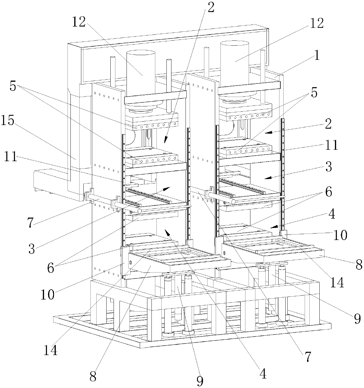
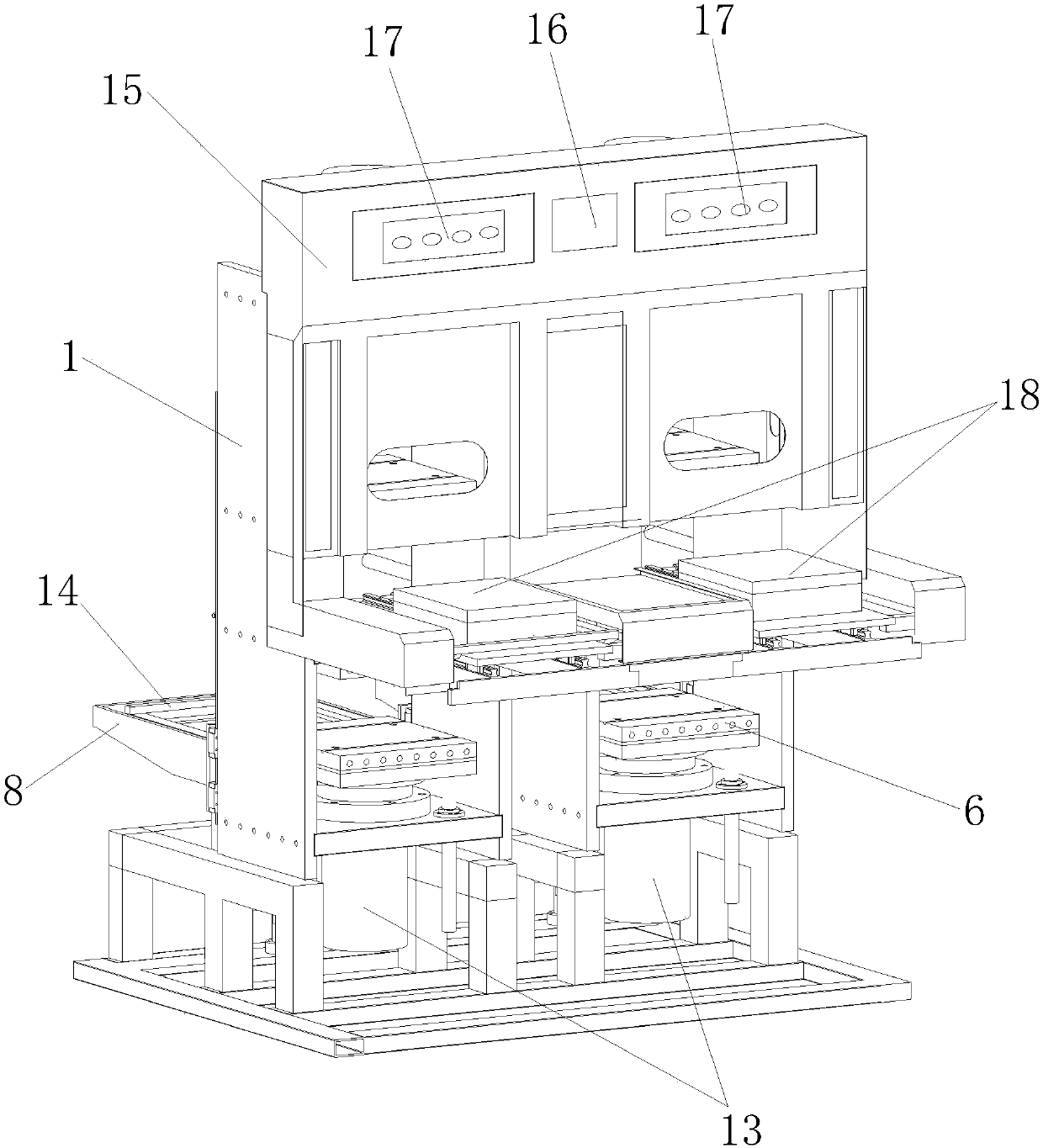
[0020] Such as figure 1 , 2 As shown, this embodiment provides a foam molding mechanical equipment, including a frame 1, which is sequentially layered with a mold heating station 2, a mold output station 3, and a mold cooling station from top to bottom. 4. The mold heating station 2 is provided with a superconducting heating plate 5 for heating the foaming mold 18, and the mold cooling station 4 is provided with an atomizing cooling plate for cooling the foaming mold 18 6. The mold output station 3 is provided with a mold ejection cylinder 7 used to drive the output of the foaming mold 18 on the side, and also includes one of the mold heating station 2, the mold output station 3, and the mold cooling station 4 A mold exchange frame 8 for conveying the foaming mold 18 between, and a lifting cylinder 9 that drives the mold exchange frame 8 to move up and down. The mold exchange frame 8 is provided with a mold sending motor 10 for conveying the foaming mold 18.
[0021] The foam molding mechanical equipment of the present invention is an integrated molding machine with heating and cooling processes. The heating and cooling processes in the EVA foaming process can be performed simultaneously, which can save labor and greatly increase productivity; the use of superconducting magnetic heating refers to the prior art The steam heating method greatly improves the heating speed; in terms of cooling, the foaming mold 18 after foaming is cooled by the atomized cooling plate 6 combined with wind, ice and water, which not only improves the cooling speed, but also saves water consumption. The water recovery rate and utilization rate are improved, and the effect of environmental protection and energy saving is good.
[0022] Further, the frame 1 is vertically provided with a support rail 11 extending to the mold heating station 2, the mold output station 3, and the mold cooling station 4, and the mold exchange frame 8 is driven by the lifting cylinder 9 along the lower edge The support rail 11 moves up and down to ensure the stability of the conveying process and accurately convey it to the channel openings of the mold heating station 2, the mold output station 3, and the mold cooling station 4, and further drive the mold sending motor 10 Next, the foaming mold 18 is input or exited from the mold heating station 2, the mold output station 3, and the mold cooling station 4.
[0023] Wherein, the top and bottom of the mold heating station 2 are respectively provided with a superconducting heating plate 5, and the top of the frame 1 is provided with a hot pressing oil cylinder 12 that controls the operation of the superconducting heating plate 5. The heating plate 5 can move up and down under the drive of the hot-pressing oil cylinder 12. When the foaming mold 18 to be heated enters the mold heating station 2, the hot-pressing oil cylinder 12 drives the superconducting heating plate 5 at the top to move and molds with the superconducting heating plate 5 at the bottom to heat the foaming mold 18. After the heating is completed, the mold is divided under the drive of the hot-pressing oil cylinder 12, and the heated foaming mold 18 can be output.
[0024] Wherein, the top and bottom of the mold cooling station 4 are respectively provided with an atomized cooling plate 6, and the lower part of the frame 1 is provided with a cold pressure oil cylinder 13 that controls the operation of the atomized cooling plate 6, and the bottom The atomizing cooling plate 6 can move up and down under the drive of the cold-pressure cylinder 13. When the foaming mold 18 that needs to be cooled enters the mold cooling station 4, the cold-pressing oil cylinder 13 drives the bottom atomized cooling plate 6 to move and closes the mold with the top atomized cooling plate 6 to cool the foaming mold 18 After the cooling is completed, the mold is divided under the drive of the cold-pressing oil cylinder 13, and the foaming mold 18 after the cooling process can be output.
[0025] Wherein, the mold exchange frame 8 is provided with a mold support bracket 14 for placing the foaming mold 18, and the bottom of the mold support bracket 14 is provided with a conveying rack, which can be extended or inserted under the drive of the mold sending motor 10 Exit mold heating station 2, mold output station 3, and mold cooling station 4. When the mold exchange frame 8 is lifted to the entrance of the mold heating station 2, the mold output station 3 or the mold cooling station 4 under the drive of the lifting oil cylinder 9, the mold sending motor 10 works and drives the conveyor frame to drive the mold support The frame 14 translates, and then drives the foaming mold 18 on the mold supporting bracket 14 to enter or exit the mold heating station 2, the mold output station 3, and the mold cooling station 4, so as to realize the fully automated heating and cooling of the foaming mold 18 And output operation, greatly saving labor and reducing labor intensity, greatly improving production efficiency.
[0026] Wherein, the frame 1 is also provided with a carrying frame 15 for carrying the output foaming mold 18, the lower part of the carrying frame 15 is flush with the mold output station 3, and the carrying frame 15 is also provided with a PLC Operation screen 16 and control buttons 17.
[0027] Preferably, the frame 1 has a three-channel structure, and the number of the mold heating station 2, the mold output station 3, and the mold cooling station 4 are two and correspondingly arranged, respectively corresponding to the two channels The die supporting bracket 14 of the dies works simultaneously under the driving of the lifting cylinder 9, which further improves the production capacity and production efficiency.
[0028] The process of applying the foam molding machinery of the present invention to EVA foam molding is as follows: the foam mold 18 containing the EVA material to be foamed is placed on the mold support bracket 14 on the mold exchange frame 8, and the lift cylinder 9 Ascends to the entrance of the mold heating station 2 channel under the driving of, and sends the foaming mold 18 into the mold heating station 2 under the drive of the mold sending motor 10, and the superconducting heating plate 5 is driven by the hot pressing oil cylinder 12 The mold is closed and the foaming mold 18 is heated. After the heating is completed, the superconducting heating plate is divided into 5 parts. The mold sending motor 10 moves to withdraw the foaming mold 18 to the mold exchange frame 8, and the lifting cylinder 9 continues to move to exchange the mold frame 8. Transported to the entrance of the mold cooling station 4 channel, and driven by the mold sending motor 10 to send the foaming mold 18 into the mold cooling station 4, driven by the cold pressure cylinder 13, the atomization cooling plate 6 is closed The foaming mold 18 undergoes cooling treatment. After the cooling is completed, the atomized cooling plate 6 is divided into molds, the mold sending motor 10 moves to withdraw the foaming mold 18 to the mold exchange frame 8, and the lifting cylinder 9 continues to move to transport the mold exchange frame 8 to the mold At the entrance of the output station 3 channel, the foaming mold 18 is sent into the mold output station 3 under the drive of the mold sending motor 10, and the mold ejection cylinder 7 acts to output the foaming mold 18 from the mold output station 3 to the load The carrier 15 of the output foaming mold 18 completes the automatic operation of heating, cooling and output of EVA foam.
[0029] Further, it also includes a sealing baffle that can move up and down along the support rail 11 and seal the opening of the mold heating station 2. After the foaming mold 18 is sent to the mold heating station 2, the sealing baffle Closing the opening of the mold heating station 2 can further improve the heating and foaming efficiency and reduce energy consumption.

PUM

no PUM

Description & Claims & Application Information

We can also present the details of the Description, Claims and Application information to help users get a comprehensive understanding of the technical details of the patent, such as background art, summary of invention, brief description of drawings, description of embodiments, and other original content. On the other hand, users can also determine the specific scope of protection of the technology through the list of claims; as well as understand the changes in the life cycle of the technology with the presentation of the patent timeline. Login to view more.

Similar technology patents

Classification and recommendation of technical efficacy words

  • Fast heating
  • Speed up cooling

System comprising duel-fuel and after treatment for heavy-heavy duty diesel (HHDD) engines

ActiveUS10287943B1Eliminating of time lapseFast heatingInternal combustion piston enginesFuel supply apparatusDecreased carbon dioxideExhaust emission
Owner:CLEAN POWER TECH LLC

High corrosion resisting and high wearable non-crystalline iron based nano crystal cost for plasma spraying and preparation method

InactiveCN1687485ASpeed up coolingExcellent comprehensive performance of corrosion resistance and wear resistanceMetallic material coating processesIron based alloyCooling speed
Owner:UNIV OF SCI & TECH BEIJING
Why Eureka
Try Eureka