
Disc engine drive device

An engine-driven, engine technology, applied in combustion engines, machines/engines, internal combustion piston engines, etc., can solve the problems of low energy utilization, large environmental pollution, waste of component forces, etc., to maximize conversion efficiency, exhaust emissions The effect of lowering and lowering fuel consumption

Inactive Publication Date: 2018-01-26
崔建超
View PDF0 Cites 0 Cited by
  • Summary
  • Abstract
  • Description
  • Claims
  • Application Information

AI Technical Summary

Problems solved by technology

[0003] Among the four strokes, only the combustion expansion stroke is the power stroke, but in the power stroke of the cylinder engine, the force arm of the thrust guide rod relative to the engine main shaft is always changing (the change of the force arm is from zero to the maximum), and a large part of the fuel The chemical energy is wasted by the component force generated when the thrust guide rod does work relative to the main shaft of the engine, resulting in the problems of high power consumption and low energy utilization rate, followed by the disadvantages of large environmental pollution

Method used


Image

  • Disc engine drive device
  • Disc engine drive device
  • Disc engine drive device

Examples


Embodiment 1

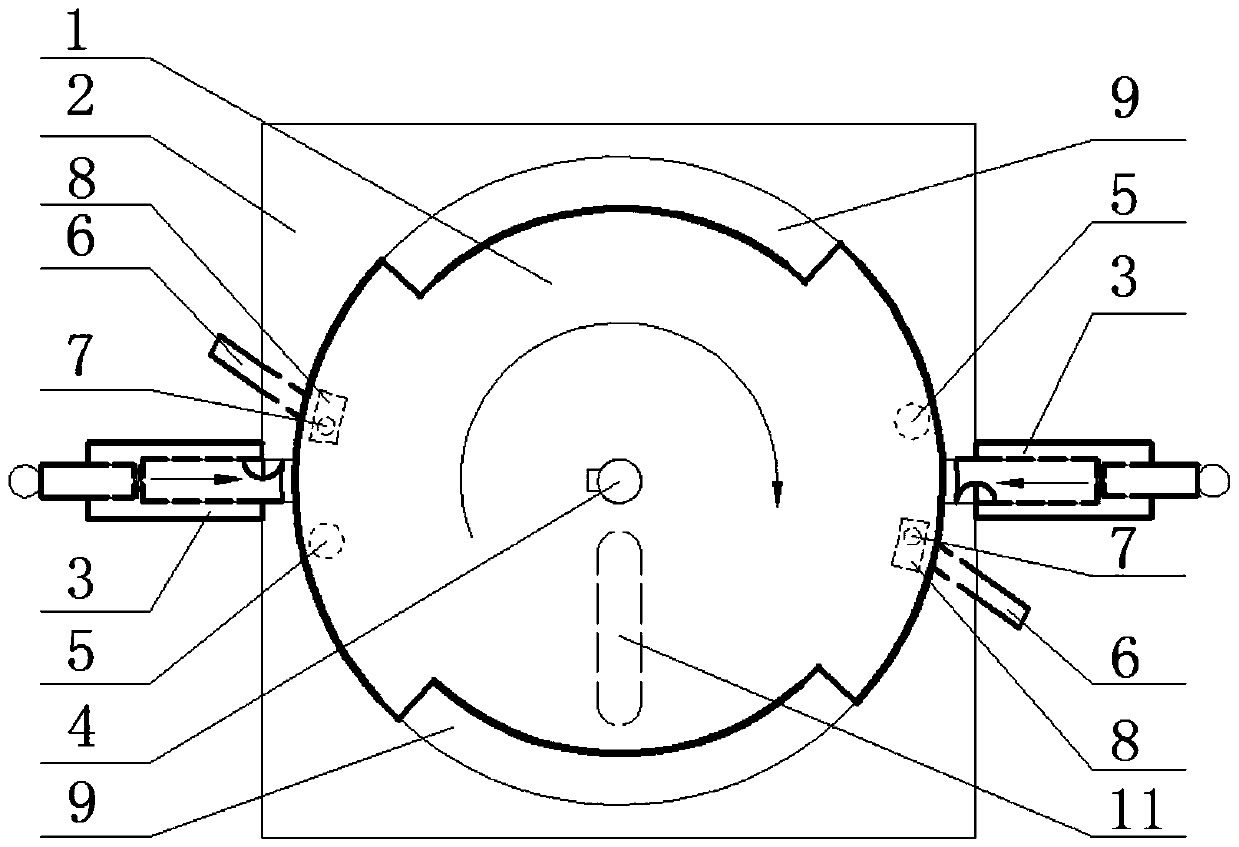
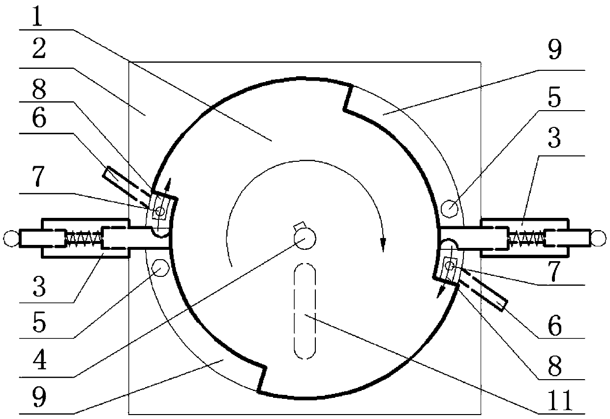
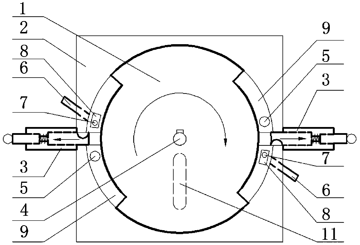
[0038] figure 1 , figure 2 , image 3 Shown separately are operating state diagrams of different stages of an ignition engine with a double combustion chamber. First, the starting device starts to drive the engine main shaft 4 to drive the flywheel 1 to rotate. When the front edge of the combustion chamber 9 reaches the position of the impact block device, the impact block (in advance, rapidly or delayed) enters the combustion chamber 9. The driving flywheel 1 continues to rotate, and the impact block divides the combustion chamber 9 into two sub-combustion chambers of the oil-gas hole combustion chamber and the exhaust hole combustion chamber. Simultaneously, the compressed oil-air mixture is pressed into the temporary gas storage chamber 8 by the oil-gas injection ignition device. The combustion chamber 9 continues to rotate, and the gas in the exhaust hole combustion chamber is discharged by the exhaust hole 5. When the intake hole combustion chamber rotates to the pos...

Embodiment 2

[0040] Figure 4 , Figure 5 , Figure 6 Shown separately are the working state diagrams of different stages of a compression ignition embodiment with dual combustion chambers. The starting device starts to drive the engine main shaft 4 to drive the flywheel 1 to rotate, and when the front edge of the combustion chamber 9 reaches the impact block device position, the impact block (in advance, rapidly or time delay) enters the combustion chamber 9. The driving flywheel 1 continues to rotate, and the impact block divides the combustion chamber 9 into two sub-combustion chambers, the oil-gas aperture combustion chamber and the exhaust aperture aperture combustion chamber. Simultaneously, the compressed high-pressure and high-temperature gas is pressed into the temporary gas storage chamber 8 by injecting oil and gas into the ignition device. The combustion chamber 9 continues to rotate, and the gas in the exhaust hole combustion chamber is discharged by the exhaust hole 5. Wh...


PUM


Abstract

The invention discloses a disc engine device with a drive force arm keeping unchanged, and mainly relates to the field of automobile engine equipment. The disc engine device is formed in the manner that an engine spindle, a drive flywheel, impact check block devices, a flywheel shell and an oil-gas spray-in ignition device cooperate with one another. A starting device provides initial power for operating of the drive flywheel. The engine spindle is mounted on the center axis of the drive flywheel and used for outputting kinetic energy outwards. Combustion chamber grooves are formed in the drive flywheel, the flywheel shell is located outside the drive flywheel, and a combustion chamber is formed by the flywheel shell and the combustion chamber grooves of the drive flywheel. The oil-gas spray-in ignition device is arranged on the flywheel shell. According to the disc engine device, a thrust force arm generated by fuel chemical energy can keep unchanged, the conversion efficiency that the chemical energy is converted into kinetic energy is maximized, and therefore thrust is maximized. According to the disc engine device, relative to the condition that a cylinder body type engine generates the same thrust, oil consumption is greatly reduced, and correspondingly, the tail gas discharge is reduced.

Description

technical field [0001] The invention relates to the field of automobile engine equipment, in particular to a disk engine driving device. Background technique [0002] An automobile engine is a device that converts fuel chemical energy into mechanical kinetic energy, and the energy conversion process is actually the process of the engine working cycle. At present, most automobile engines use a cylinder block structure to realize the conversion of fuel chemical energy into mechanical kinetic energy. The specific working process is: the mixture of fuel and air is pressed into the cylinder and ignited, the gas is heated and expanded, driving the reciprocating movement of the engine cylinder piston, which drives the connecting rod connected to the piston and the crank connected to the connecting rod to move around the center of the crankshaft Reciprocating circular motion to output power. The working process of a cylinder block engine consists of four strokes: intake, compressi...

Claims


Application Information

Patent Timeline
IPC IPC(8): F02B53/00F02B53/02
CPCY02T10/12
Inventor 崔建超
Owner 崔建超
Learn More