
Method for constructing 3D topography of weld seam based on grid structure laser

A technology of grid structure and construction method, applied in the direction of using optical devices, optical testing defects/defects, measuring devices, etc., can solve the problems of low system detection efficiency, long acquisition time, violation of fast surface topography detection, etc.

Active Publication Date: 2018-01-26
ZHONGBEI UNIV
View PDF10 Cites 21 Cited by
  • Summary
  • Abstract
  • Description
  • Claims
  • Application Information

AI Technical Summary

Problems solved by technology

And generally equipped with a detection system, the cost is high, which will lead to an increase in system cost, which is not conducive to the industrialization of the weld detection system
[0009] 2. The existing laser shape measurement sensors mostly use a single-line laser to scan the surface to be measured. The surface information of the object obtained by a single frame image is very limited, and the length of the general weld is long, and the one-dimensional scanning acquisition of a single-line laser takes more time. , coupled with the subsequent need for software platforms for data processing, will lead to low detection efficiency of the entire system, contrary to the original intention of rapid surface topography detection
[0010] 3. Existing laser shape measurement sensors generally use a fixed installation method. Once the installation height exceeds the range set by the sensor, it will bring a large error
The laser shape measurement sensors of most companies generally use the measurement software developed by our company. Although they have certain versatility, the detection of various components in the industry will largely limit the independent development of the system.

Method used


Image

  • Method for constructing 3D topography of weld seam based on grid structure laser
  • Method for constructing 3D topography of weld seam based on grid structure laser
  • Method for constructing 3D topography of weld seam based on grid structure laser

Examples


Embodiment Construction

[0106] The following examples are only preferred technical solutions of the present invention, and are not intended to limit the present invention in any way. Various modifications and variations of the present invention will occur to those skilled in the art. Any modifications, equivalent replacements, improvements, etc. made within the spirit and principles of the present invention shall be included within the protection scope of the present invention.

[0107] This embodiment uses a hand-held grid-shaped laser shape measurement sensor to construct the three-dimensional topography of the weld. For ease of description, the weld is placed in a spatial coordinate system XYZO In the three-dimensional space of , and set the longitudinal direction of the weld to be X Axial direction, section direction is Y axis direction, the height is Z axis direction.

[0108] The grid laser shape measurement sensor consists of a semiconductor grid structure laser with a wavelength of 650nm...


PUM


Abstract

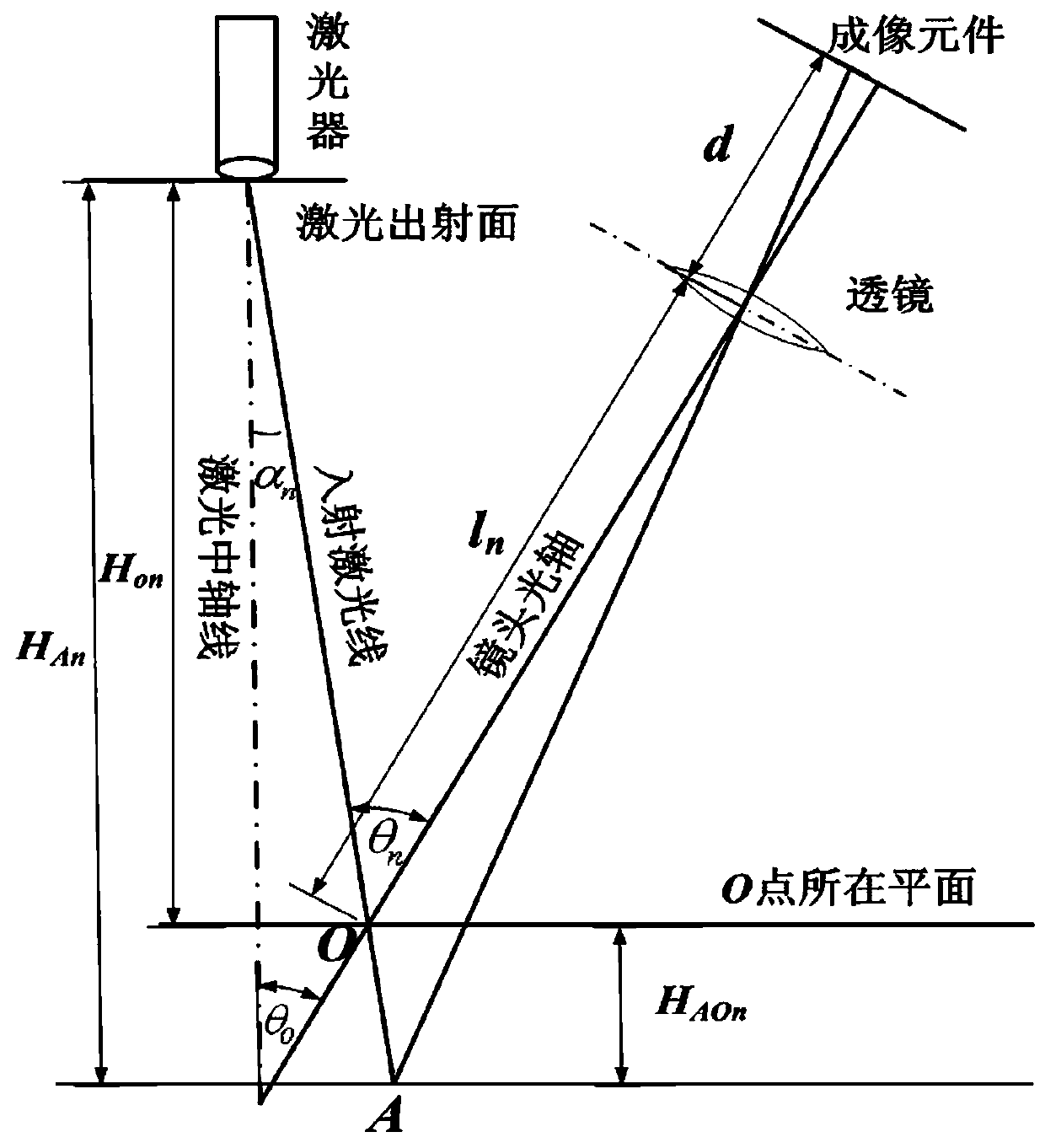
The invention discloses a method for constructing the 3D topography of a weld seam based on a grid structure laser. The method includes the following steps: configuring a grid-structured laser and anindustrial camera at a fixed angle so as to constitute a shape measurement sensor, a grid-shaped structured light emitted by a grid-structured laser forming a grid-shaped light spot on the surface ofa to-be-detected component and being reflected or scattered by the surface of the to-be-detected component to enter the industrial camera for performing imaging, an image being processed to a skeletonimage which is vertical to the longitudinal direction of the weld seam, calculating the absolute heights between respective points on the surface of the weld seam and the laser emitting surface of the grid-structured laser, based on the absolute height data, constructing the profile of the surface of the weld seam. According to the invention, the method can acquire image information on the surface of the weld seam by using the laser shape measurement sensor in hand, can construct the 3D topography of the weld seam on the surface of the component in a rapid and accurate manner, and automatically and rapidly detect the topography of the weld seam.

Description

technical field [0001] The invention belongs to the technical field of weld detection. The invention relates to a fast three-dimensional measurement method for the surface weld appearance of a component by using a grid structure laser. Background technique [0002] The quality of the weld directly determines the final quality and performance safety of the product. The inspection of welding quality, on the one hand, can ensure the manufacturing quality of welded structural parts, improve product reliability, and ensure its safe operation; on the other hand, it is conducive to improving welding technology and product quality. [0003] With the development of industrial automation and welding in various important industrial fields, the use of advanced equipment for weld quality inspection has become an important research content in the field of welding. At present, the content of welding quality inspection mainly includes: weld appearance and surface defect inspection, weld i...

Claims


Application Information

Patent Timeline
IPC IPC(8): G01B11/24G01N21/88
Inventor 李志勇刘航贾娜娜仁杰亮薛春霞
Owner ZHONGBEI UNIV
Learn More