Method for ranging single terminal fault of single outlet power transmission line based on opposite terminal bus reflected wave identification

A technology for opposing busbars and transmission lines, applied in the direction of fault locations, etc., can solve problems such as adverse effects, and achieve the effect of improving accuracy, improving accuracy, and improving accuracy

Active Publication Date: 2018-01-26
YUNNAN POWER GRID +2
View PDF9 Cites 16 Cited by
  • Summary
  • Abstract
  • Description
  • Claims
  • Application Information

AI Technical Summary

Problems solved by technology

[0004] The technical problem to be solved in the present invention is to provide a single-end fault location method for a single-outlet transmission line based on the reflected wave id...

Method used


Image

  • Method for ranging single terminal fault of single outlet power transmission line based on opposite terminal bus reflected wave identification
  • Method for ranging single terminal fault of single outlet power transmission line based on opposite terminal bus reflected wave identification
  • Method for ranging single terminal fault of single outlet power transmission line based on opposite terminal bus reflected wave identification

Examples


Embodiment 1

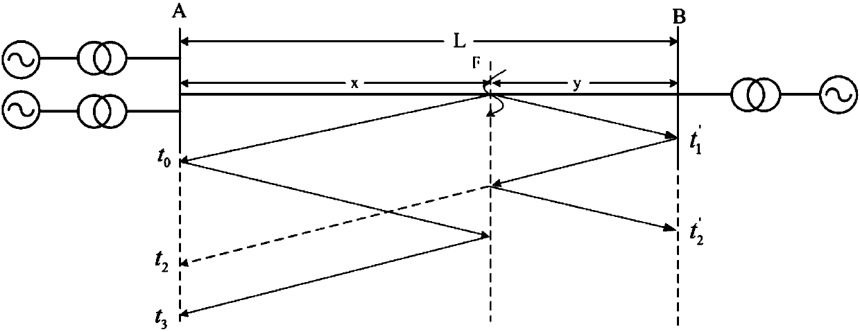
[0035] Embodiment 1: A single-end fault location method for a single-outlet transmission line based on the reflected wave identification of the opposite-end busbar. When a fault occurs on the transmission line, the three-phase current of the line is obtained from the measurement point at the head end of the line, and obtained separately Its zero-mode component and line-mode component; for the zero-mode component and line-mode component, obtain the modulus maximum value through continuous wavelet transform, and determine the time t for the zero-mode current traveling wave to reach the head-end measurement point 0 , The time t for the line-mode current traveling wave to reach the head-end measurement point 1 ;According to the principle that the zero-mode current traveling wave polarity of the opposite-end bus reflected wave of the single-outlet transmission line is opposite to the initial traveling wave polarity, determine the wave head of the zero-mode current traveling wave opp...

Embodiment 2

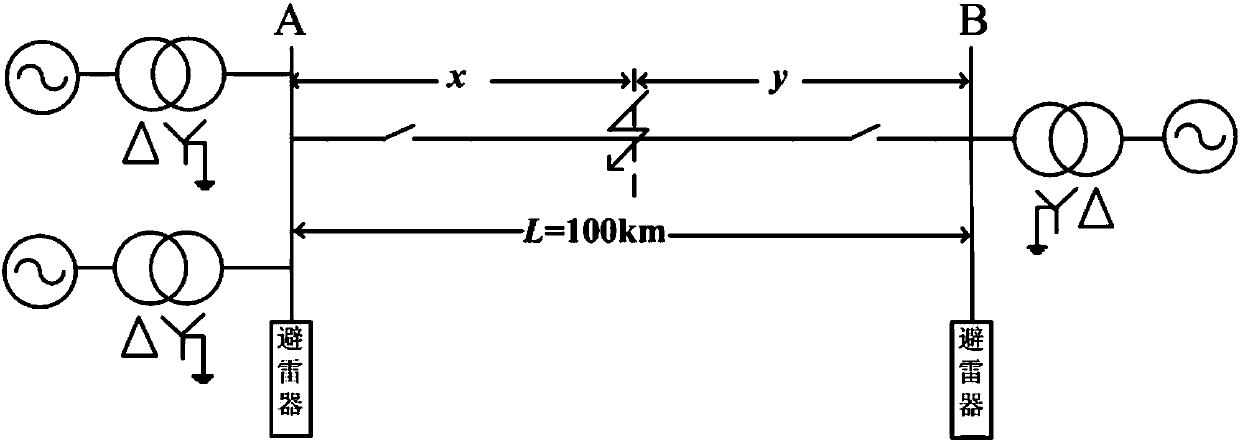
[0054] Embodiment 2: as figure 2 The simulation model of the 500kV transmission line shown has a total length of 100km. Assume that a phase A ground fault occurs 70km away from point A.

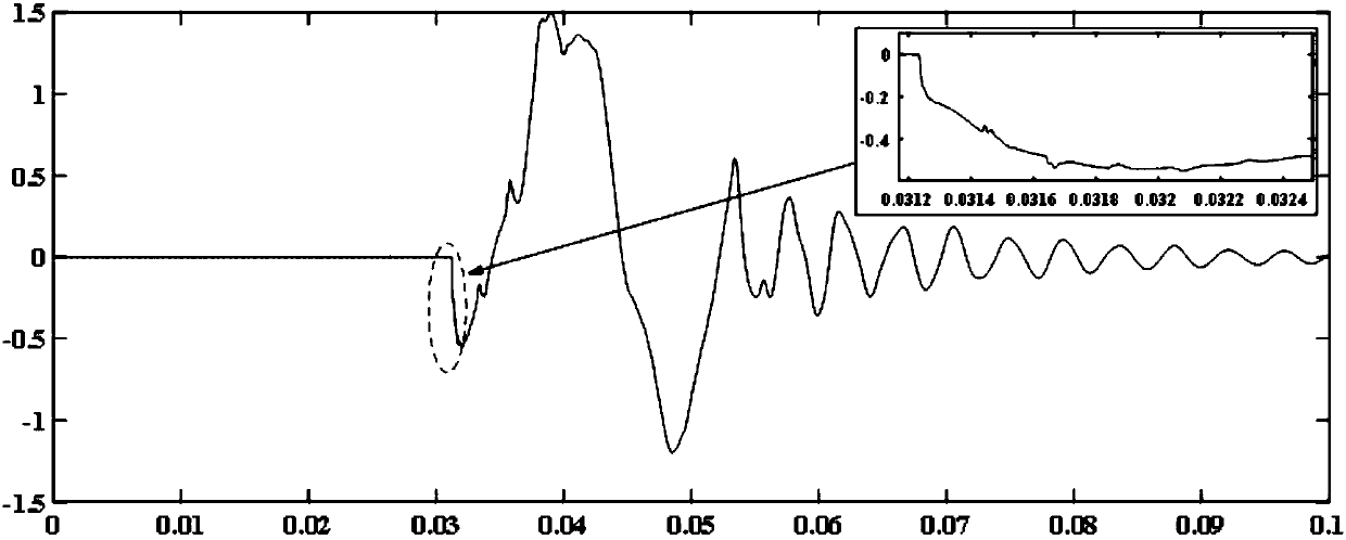
[0055] The three-phase current traveling waves are obtained from the measurement points at both ends of the transmission line, and the calculated zero-mode current waveforms and line-mode current traveling waves are as follows: image 3 , Figure 4 shown. The modulus maximum value obtained by using the wavelet transform through the matlab software is as follows Figure 5 , Figure 6 shown. Obtain the time t when the zero-mode component arrives at the measurement end 0 and the time t when the line mode arrives at the measuring end 1 They are:

[0056] t 0 =0.0312330472103

[0057] t 1 =0.0312320171674

[0058] According to the reflection wave of the opposite end bus determined by the zero mode, the reflection wave of the line mode opposite end bus is identified as follows: Figur...

Embodiment 3

[0063] Embodiment 3: as figure 2 The simulation model of the 500kV transmission line shown has a total length of 100km. Assume that a phase A ground fault occurs 30km away from point A.

[0064] The three-phase current traveling waves are obtained from the measurement points at both ends of the transmission line, and the calculated zero-mode current waveforms and line-mode current traveling waves are as follows: Figure 7 , Figure 8 shown. The modulus maximum value obtained by using the wavelet transform through the matlab software is as follows Figure 9 , Figure 10 shown. Obtain the time t when the zero-mode component arrives at the measurement end 0 and the time t when the line mode arrives at the measuring end 1 They are:

[0065] t 0 =0.0310991416309

[0066] t 1 =0.0310961373391

[0067] According to the reflection wave of the opposite end bus determined by the zero mode, the reflection wave of the line mode opposite end bus is identified as follows: Fig...


PUM


Abstract

The invention relates to a method for ranging the single terminal fault of a single outlet power transmission line based on opposite terminal bus reflected wave identification, and belongs to the technical field of fault ranging of power systems. When a power transmission line has a fault, the method includes the following steps: acquiring three-phase currents of the line from a head terminal of the line and separately resolving a zero modulus component and an aerial modulus component of the three-phase currents; separately performing continuous wavelet transform on the zero modulus componentsand the aerial modulus components to resolve the modulus maxima thereof, and separately determining the time t<0>, t<1> when the zero modulus current travelling wave and the aerial modulus current travelling wave arrive at the measurement point at the head terminal; determining the wave head of the zero modulus current travelling wave of the opposite terminal bus reflected wave, determining the time t<2> when the zero modulus current reflected wave which is reflected by the opposite terminal bus arrives at the measurement point at the head terminal; based on the determined wave head of the zero modulus current travelling wave of the opposite terminal bus reflected wave, determining the wave head of the opposite terminal bus reflected wave that corresponds to the aerial modulus current travelling wave, and determining the time t3 when the measurement point arrives at the head terminal; and resolving the fault distance x by using the wave head of the aerial modulus current travelling wave and a novel fault ranging formula of the wave head of the opposite terminal bus reflected wave.

Description

technical field [0001] The invention relates to a single-end fault distance measurement method of a single-outlet power transmission line based on the reflected wave identification of opposite-end busbars, and belongs to the technical field of power system fault distance measurement. Background technique [0002] Transmission lines are an important part of the power system and occupy a very important position. With the development of my country's electric power industry, the transmission network is becoming more and more complex. How to quickly and accurately determine the fault location when the transmission line fails has become a hot topic in the contemporary electric power industry. Quickly and accurately determining the fault location helps to repair the fault line in time, reduces the pressure of line inspection and greatly shortens the fault time. It is also very important for the safe, stable and economical operation of the power system. In the traditional single-en...

Claims


Application Information

Patent Timeline
IPC IPC(8): G01R31/08
Inventor 方毅李本瑜石恒初张琳波游昊杨远航陈剑平罗吉翟海燕赵明束洪春张瑀明李录照赵云鹏
Owner YUNNAN POWER GRID
Why Eureka
Try Eureka