Battery case having radiating tube and battery thereof
A heat pipe and battery case technology, applied in secondary batteries, battery pack components, circuits, etc., can solve the problems of uneven battery heating, reduced battery life, and long charging time.
- Summary
- Abstract
- Description
- Claims
- Application Information
AI Technical Summary
Problems solved by technology
Method used
Image

Examples
Embodiment 1
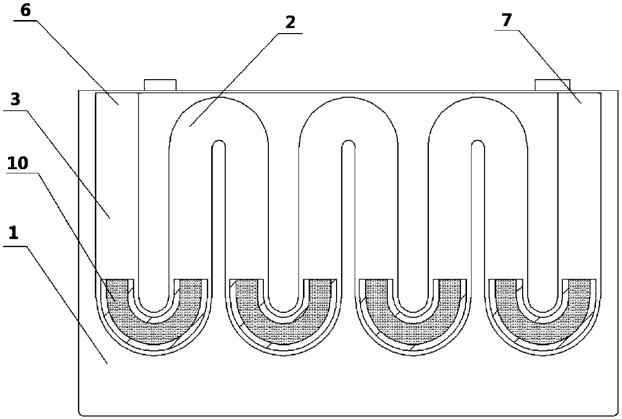
[0030] This embodiment provides a battery case and a battery with a serpentine heat dissipation pipe. The outer surface of the battery case and the battery is provided with a heat dissipation pipe. During the use of the battery, the condensed working medium inside the heat dissipation pipe can evenly heat the surface of the battery. , keep the temperature of each part of the battery consistent, solve the problem of heat accumulation and uneven conduction inside the battery, and quickly conduct the heat generated by the battery, so that the battery can be charged and discharged quickly, increase the number of times of battery charge and discharge, and prolong the service life of the battery .
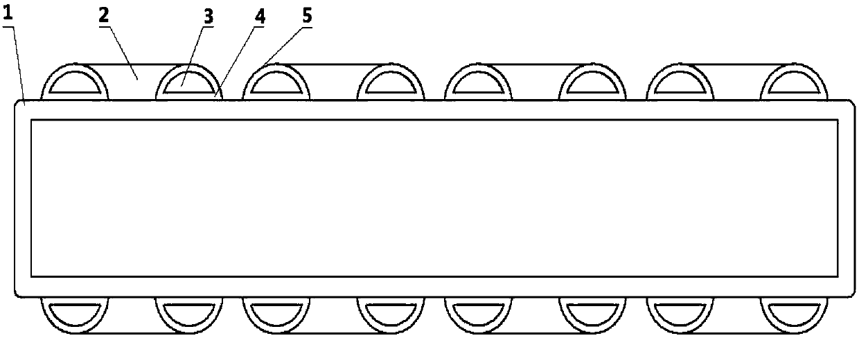
[0031] Specifically, combined with figure 1 and figure 2 shown. figure 1 It is a cross-sectional schematic diagram of a battery case with a serpentine heat pipe; figure 2 It is a schematic diagram of a longitudinal section of a battery with serpentine heat pipes.
[0032] The batte...
Embodiment 2
[0038] This embodiment provides a battery case and a battery in which heat pipes are welded to the outer surfaces of the four side plates.
[0039] Specifically, combined with image 3 as shown, image 3 It is a schematic diagram of a battery with heat pipes welded on the outer surfaces of the four side plates.
[0040] The difference from Example 1 is that the heat dissipation pipes 2 are respectively connected to the outer surfaces of the front, rear, left, and right side plates of the battery case body 1 by welding. same. Compared with Embodiment 1, the design of this embodiment increases the heat dissipation area of the battery and further improves the heat dissipation efficiency of the battery. .
Embodiment 3
[0042] This embodiment provides a battery case and a battery in which the heat dissipation pipe 2 is integrally formed with the front side plate of the battery.
[0043] Specifically, combined with Figure 4 as shown, Figure 4 It is a schematic diagram of the battery in which the heat pipe is integrally formed with the front side plate.
[0044] The difference from Embodiment 1 is that the battery case and the heat dissipation pipe 2 of the battery provided in this embodiment are integrally formed with the outer surface of the front side plate of the battery case body 1, and a condensing working medium inlet 6 and a condensing fluid inlet 6 are provided at both ends of the heat dissipation pipe. The working medium outlet 7, other implementations of this embodiment are the same as those of Embodiment 1. In this embodiment, the integrated design of the heat dissipation pipe 2 and the battery case body 1 omits the process steps of welding or pasting with conductive double-side...
PUM
 Abstract
Description
Claims
Application Information
 - R&D
- Intellectual Property
- Life Sciences
- Materials
- Tech Scout
- Unparalleled Data Quality
- Higher Quality Content
- 60% Fewer Hallucinations
Browse by: Latest US Patents, China's latest patents, Technical Efficacy Thesaurus, Application Domain, Technology Topic, Popular Technical Reports.
© 2025 PatSnap. All rights reserved.Legal|Privacy policy|Modern Slavery Act Transparency Statement|Sitemap|About US| Contact US: help@patsnap.com