Electromechanical assembly comprising electrical machine coupled to reduction gear

A technology of electromechanical components and deceleration devices, which is applied in the direction of electric components, electromechanical devices, electrical components, etc., can solve the problems of spline wear and service life, and achieve the effect of improving retention

Inactive Publication Date: 2018-01-26
MOTEURS LEROY SOMER
View PDF8 Cites 2 Cited by
  • Summary
  • Abstract
  • Description
  • Claims
  • Application Information

AI Technical Summary

Problems solved by technology

This misalignment causes spline wear and is a source of noise an

Method used


Image

  • Electromechanical assembly comprising electrical machine coupled to reduction gear
  • Electromechanical assembly comprising electrical machine coupled to reduction gear
  • Electromechanical assembly comprising electrical machine coupled to reduction gear

Examples


Embodiment Construction

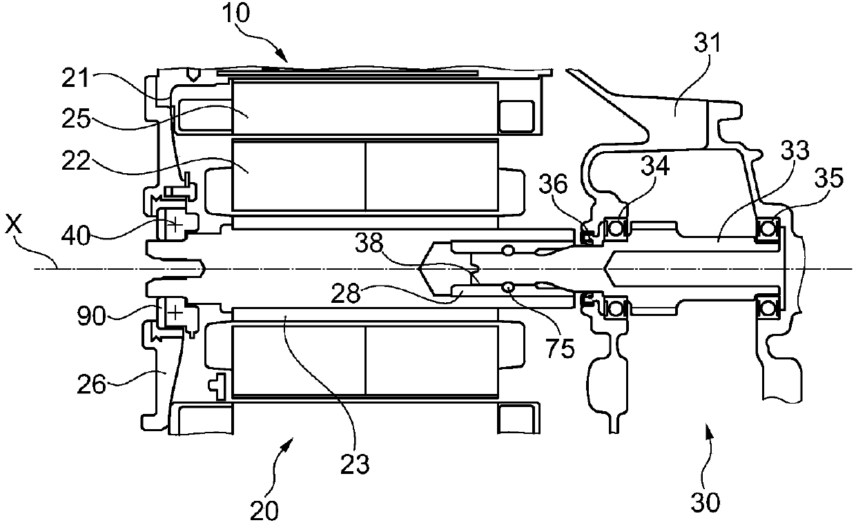
[0023] figure 1 The assembly 10 shown in includes a motor 20 and a reduction gear 30 coupled to the machine 20.

[0024] The machine 20 and the reduction gear 30 include respective housings 21 and 31 connected together by bolts, for example.

[0025] In the example considered, the machine 20 is an electric motor and includes a rotor 22, the shaft 23 of which can rotate about the axis X.

[0026] The rotor 22 is located in the stator 25.

[0027] The machine 20 may be a motor with permanent magnets.

[0028] The shaft 23 is supported at the rear by a bearing 40 which is carried by the flange 26 of the machine 20.

[0029] The reduction gear 30 includes an input shaft 33 which is guided forward and backward through corresponding bearings 34 and 35.

[0030] Bearing 40, bearing 34 and bearing 35 are preferably ball bearings.

[0031] As shown, a lip seal 36 may be provided, which is applied to the shaft 33 in front of the bearing 34. The seal can hold the grease of the reduction gear.

[0032...


PUM


Abstract

The invention relates to an electromechanical assembly comprising an electrical machine (20) coupled to a reduction gear (30), said electrical machine comprising a single bearing (40) at the rear. According to the invention, either the electrical machine or the reduction gear is equipped with a male shaft (33), while the other is equipped with a female shaft (23) mounted on the male shaft. In addition, the shafts have conical bearing surfaces (56, 59), and the assembly comprises an elastically deformable element (90) that biases the bearing surfaces axially relative to one another until they engage with one another.

Description

Technical field [0001] The present invention relates to electromechanical components including an electric motor and a reduction gear, and more particularly, but not exclusively, the present invention relates to these electromechanical components: the electric motor in these electromechanical components is a motor, particularly a traction motor of a motor vehicle. Background technique [0002] It is known to assemble an electric motor and a reduction gear by means of a splined coupling, wherein one of the shafts is a male shaft and the other is a female shaft, and the female shaft usually has a hollow end and a belt cover Type bushing shaft. In order to allow the assembly of each shaft, there must be clearance at the spline, and the clearance is a source of wear and noise. The motor may include only a single bearing at the rear, wherein the shaft of the motor is guided by the shaft of the reduction gear at the front, and the shaft of the reduction gear may be supported by two be...

Claims


Application Information

Patent Timeline
IPC IPC(8): F16D1/10H02K7/00H02K7/116
CPCF16D1/101F16C19/06F16C19/546F16C25/083F16C2326/20F16C2380/26F16C2380/27F16D2001/103F16D2300/08F16D2300/22H02K7/003H02K7/116
Inventor 迪迪埃·卡尔梅特塞缪尔·克希林
Owner MOTEURS LEROY SOMER
Why Eureka
Try Eureka