Thermostatic device for controlling circulation of fluid, and thermostatic valve including such device

A technology for constant temperature equipment and fluid control, which is applied in temperature control, non-electric variable control, control/regulation systems, etc., and can solve problems such as high implementation costs

Inactive Publication Date: 2018-01-26
VERNET SA
View PDF11 Cites 4 Cited by
  • Summary
  • Abstract
  • Description
  • Claims
  • Application Information

AI Technical Summary

Problems solved by technology

However, this solution has proven to be restrictive and costly to implement, since it has limited mechanical strength, especially in the long term, and has a solid design, because of the impact on the outer diameter of the stop and / or the thermostatic element. Any change in the size of the need to completely change the size of the stop

Method used


Image

  • Thermostatic device for controlling circulation of fluid, and thermostatic valve including such device
  • Thermostatic device for controlling circulation of fluid, and thermostatic valve including such device
  • Thermostatic device for controlling circulation of fluid, and thermostatic valve including such device

Examples


Embodiment Construction

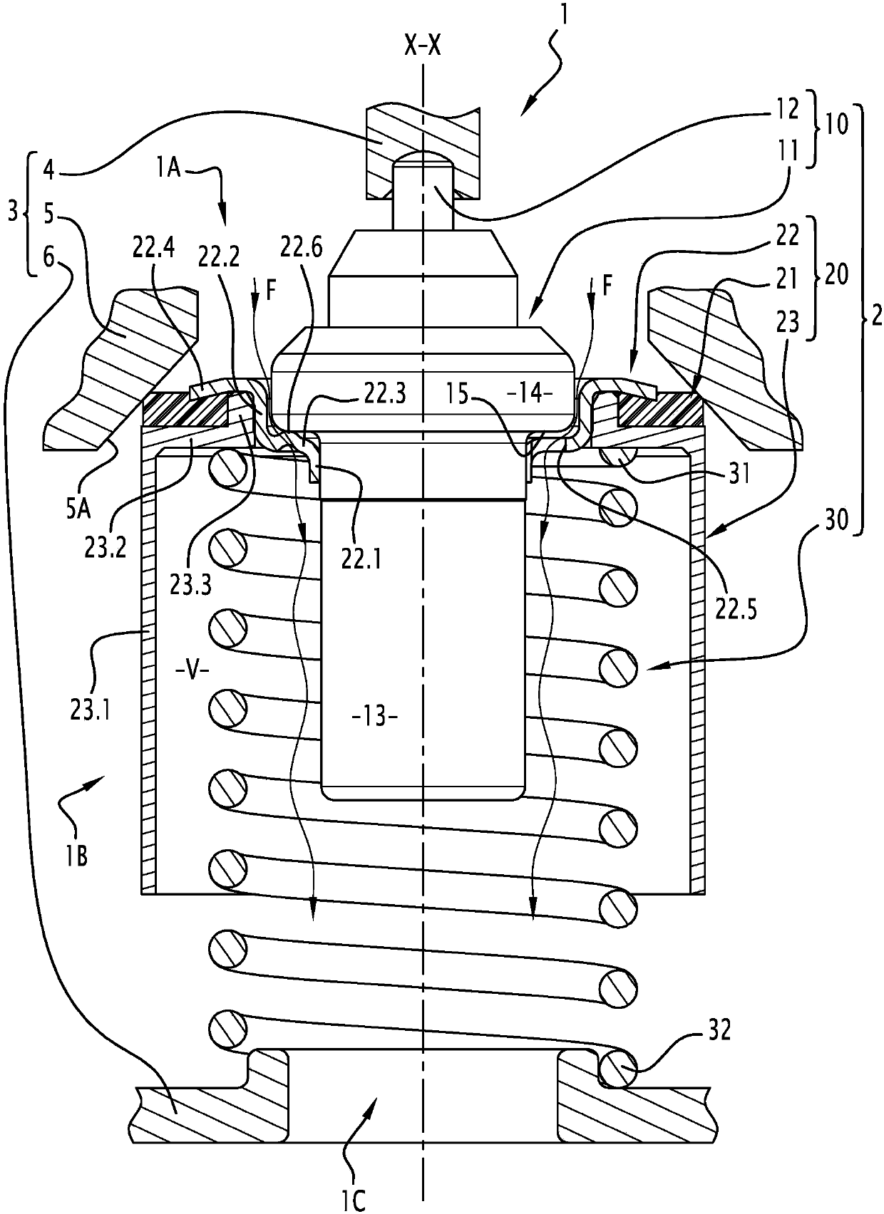
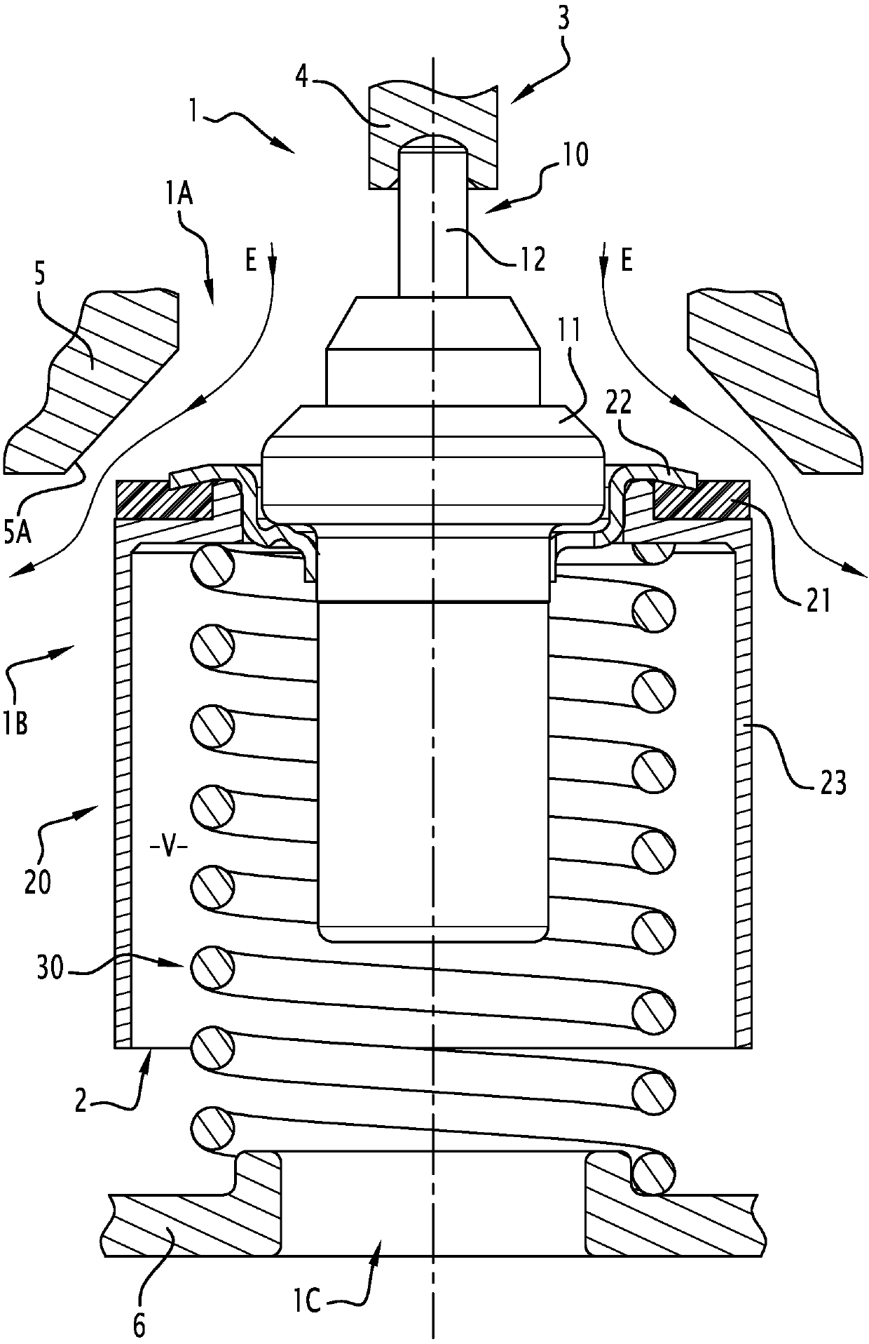
[0019] Figure 1 to Figure 6 A valve 1 is shown comprising a thermostatic device 2 for regulating the flow of fluid. This fluid is usually a coolant or a heat transfer fluid. For example, valve 1 belongs to the secondary circuit of a cooling assembly of a heat engine, in particular a motor vehicle engine, however, as mentioned in the preamble of this document, this example is not limiting.

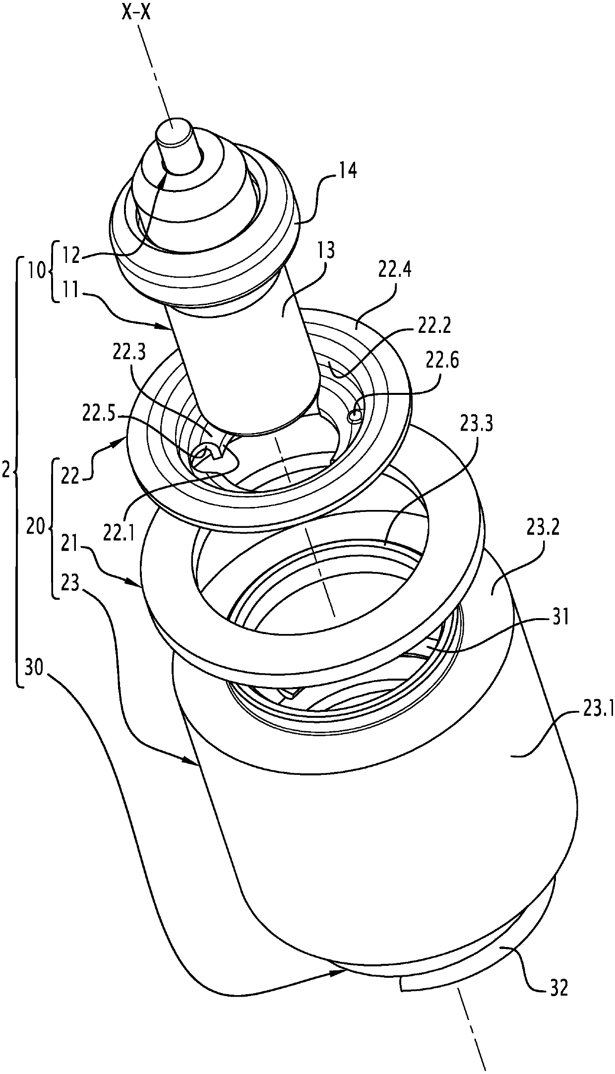
[0020] Thermostat 2 in image 3 are shown alone, however in figure 1 and figure 2 , the device 2 is arranged in the parts 4, 5 and 6 of the housing 3 of the valve 1, it can be noted that these parts 4, 5 and 6 are fixed relative to each other, and at the same time, in the valve 1 such as figure 1 and figure 2 When used as shown, the parts are, for example, integrated with each other and / or secured to each other. In fact, in figure 1 and figure 2 In , the parts 4, 5 and 6 of the housing 3 are only partially and schematically shown, and their embodiments are not restrictive for th...


PUM


Abstract

The invention relates to a device (2) which includes a thermostatic element (10), as well as a stopper (20), which is axially movable relative to a stationary seat (5A) of a housing (3) so as to openand close a passage for the circulation of the fluid and which is connected to a body (11) of the thermostatic element so that, during the expansion of a thermodilatable material contained in said body, said body drives the stopper relative to the seat, a piston (12) of the thermostatic element, which is immersed in said thermodilatable material, being securely connected to the housing. In order for the integration of an outflow in the stopper to be economical, efficient and reliable, the stopper includes, as two separate parts: an insert (22) for receiving the body of the thermostatic element, which is provided with outflow means (22.5, 22.6), suitable for, regardless of the axial position of the stopper (20) relative to the housing (3), allowing the fluid to flow freely between the bodyof the thermostatic element and the inner surface of the insert and to pass through the insert in order to reach the outer surface thereof; and a sleeve (23) for lining the outside of the body of thethermostatic element, which is securely attached to the insert, surrounding the entire periphery of the body of the thermostatic element at a distance so as to define radially between said body of thethermostatic element and the sleeve a free space (V) for fluid circulation passing through the outflow means.

Description

technical field [0001] The invention relates to a thermostatic device and a thermostatic valve comprising such a device. [0002] The invention relates in particular to thermostatic devices and thermostatic valves for use in cooling circuits of heat engines, especially motor vehicles, heavy trucks, two-wheeled vehicles, and stationary engines. However, the scope of this application does not limit the invention, since the devices and valves according to the invention can be used in other various fluid circuits, such as gearbox cooling circuits, water circuits, oil circuits, etc. Background technique [0003] In such fluid circuits, such thermostatic valves are used to regulate the flow of fluid based on the temperature of the fluid, ie to distribute the fluid into different paths of the circuit. These valves are called thermostatic valves because the movement of their internal seal relative to the seat associated with the housing of the valve is controlled by a thermostatic ...

Claims


Application Information

Patent Timeline
Patent Type & Authority Applications(China)
IPC IPC(8): G05D23/02
CPCG05D23/022
Inventor 威廉·达西尔瓦
Owner VERNET SA
Why Eureka
Try Eureka