Water and land combined floating type track conveying system
A conveying system and floating technology, applied in the field of floating rail conveying system, can solve the problems of poor timeliness and slow speed, and achieve the effect of promoting urbanization process, fast driving speed and improving transportation capacity
- Summary
- Abstract
- Description
- Claims
- Application Information
AI Technical Summary
Problems solved by technology
Method used
Image
Examples
Embodiment 1
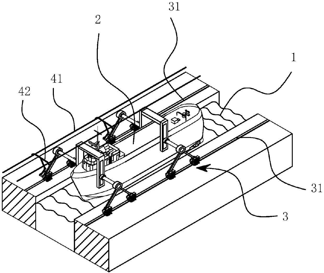
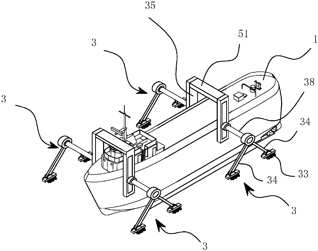
[0034] see Figure 1-Figure 5 , the floating track 31 conveying system combining water and land in this embodiment includes a hull 2 for driving in the waterway 1, and both sides of the hull 2 are provided with a track driving device 3 for pushing the hull 2, and the track driving device 3 Traveling on the track 31, the track 31 is fixed on the ground, and the track driving device 3 is fixed on the hull 2 through a connecting column.
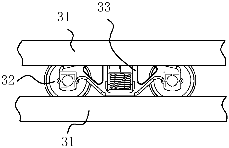
[0035] Described track driving device 3 comprises driving wheel 32, driving module, driving chassis 33 and cantilever 34, and driving wheel 32 is rotatably installed on driving chassis 33, and one end of cantilever 34 connects driving chassis 33, and the other end of cantilever 34 connects an end of connecting column , the other end of the connecting column 38 is fixed on the hull 2, and the driving module is connected to the driving wheel 32, so as to drive the driving wheel 32 to rotate relative to the track 31. One end of the connectin...
Embodiment 2
[0042] see Image 6 The floating track 31 conveying system combined with water and land in this embodiment is basically the same as that of Embodiment 1, the difference is that: the upper and lower rows of driving wheels 32 are rotatably mounted on the driving chassis 33, and the upper and lower rows of driving wheels 32 are respectively rotatably mounted on On the upper support 331 and the lower support 332, the track 31 is clamped between the upper and lower rows of drive wheels 32, and a clamping mechanism for clamping the upper and lower rows of drive wheels 32 on the track 31 is arranged between the upper and lower rows of drive wheels 32. mechanism, the clamping mechanism adopts an oil cylinder 39, and the cylinder body of the oil cylinder 39 and the piston rod of the oil cylinder 39 are respectively connected to the upper bracket 331 and the lower bracket 332.
Embodiment 3
[0044] see Figure 7 The floating track 31 conveying system combined with water and land in this embodiment is basically the same as that in Embodiment 1, the difference is that a crossbeam 51 is slidably installed on the hull 2, and the two ends of the crossbeam 51 are respectively fixed to the connecting columns 38 on both sides of the hull 2. the other end of the By adopting this structure, the rigidity of the connecting columns on both sides of the hull 2 can be improved, and the overall strength can be improved.
PUM
 Abstract
Description
Claims
Application Information
 - R&D
- Intellectual Property
- Life Sciences
- Materials
- Tech Scout
- Unparalleled Data Quality
- Higher Quality Content
- 60% Fewer Hallucinations
Browse by: Latest US Patents, China's latest patents, Technical Efficacy Thesaurus, Application Domain, Technology Topic, Popular Technical Reports.
© 2025 PatSnap. All rights reserved.Legal|Privacy policy|Modern Slavery Act Transparency Statement|Sitemap|About US| Contact US: help@patsnap.com


